Self-clamping structure for solving short-circuit resistance problem of amorphous alloy transformers

a technology of amorphous alloy transformers and self-clamping, which is applied in the field of transformers, can solve the problems of low-voltage coils that cannot be tightly expanded by the iron core, poor resistance to short circuits, and prone to excessive deformation or short-circuit damage, so as to prevent radial deformation of the coil and reduce the cost of manufacturing the transformer.

Active Publication Date: 2021-01-26
JIANGSU HUAPENG TRANSFORMER
View PDF20 Cites 0 Cited by
  • Summary
  • Abstract
  • Description
  • Claims
  • Application Information

AI Technical Summary

Benefits of technology

[0004]The technical problem to be solved by the present disclosure is to propose a self-clamping structure for solving the short-circuit resistance problem of amorphous alloy transformers. This concept and structure solve the disadvantages such as having complicated structure and cumbersome winding operation and being material consuming and time consuming described in the background art, and are both simple and reliable.
[0007]Still further, when short-circuit force is large, outer sides of the A-phase coil and the C-phase coil described in the present disclosure are each provided with a splint (clamp plate); and the splint and the low-voltage coil of corresponding phase constitute a splint pair and are bound by a binding strap, to clamp and fix the high-voltage coil of the corresponding phase. The formed “splint pair” can tightly clamp and fix the coil to greatly increase the ability of the coil to resist short circuit. Naturally, when the short-circuit force is small, the splints at the outer sides of the A- and C-phase coils can be eliminated, and the coils may be reinforced only with the banding straps.
[0011]The present disclosure has the following beneficial effects: 1. the solidified low-voltage foil-wound coil and the epoxy plate are used as splints, to prevent radial deformation of the coil during short-circuiting; 2. the high- and low-voltage coils are bound together by a binding strap to prevent the axial displacement of the coils during short-circuiting; 3. the cost of manufacturing the transformer is greatly reduced (the annual performance may amount to 500 million RMB or more, when estimated based on the actual production of 2.5-3.0 million amorphous transformers in China).

Problems solved by technology

Since an iron core of the amorphous transformer is not capable of bearing force and the coil of the amorphous transformer is mostly in a rectangular shape, the low-voltage coil cannot be tightly expanded by the iron core of the amorphous transformer, and a straight-side portion of the rectangular coil has a poor resistance to short circuit.
When the transformer is short-circuited, the coil, subjected to actions of an axial force and a radial force, is prone to excessive deformation or short-circuit damage.
However, all of these methods have disadvantages such as being material consuming and time consuming, and having complicated structures and processes, cumbersome winding operation, poor reliability, etc.

Method used


Image

  • Self-clamping structure for solving short-circuit resistance problem of amorphous alloy transformers
  • Self-clamping structure for solving short-circuit resistance problem of amorphous alloy transformers
  • Self-clamping structure for solving short-circuit resistance problem of amorphous alloy transformers

Examples


Embodiment Construction

[0019]The present disclosure will now be described in further detail with reference to the accompanying drawings and preferred embodiments. These drawings are simplified schematic diagrams that only schematically illustrate the basic structure of the present disclosure, and thus only show the configurations relevant to the present disclosure.

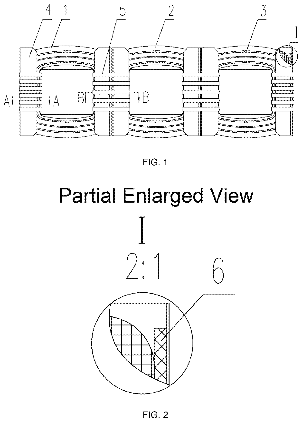
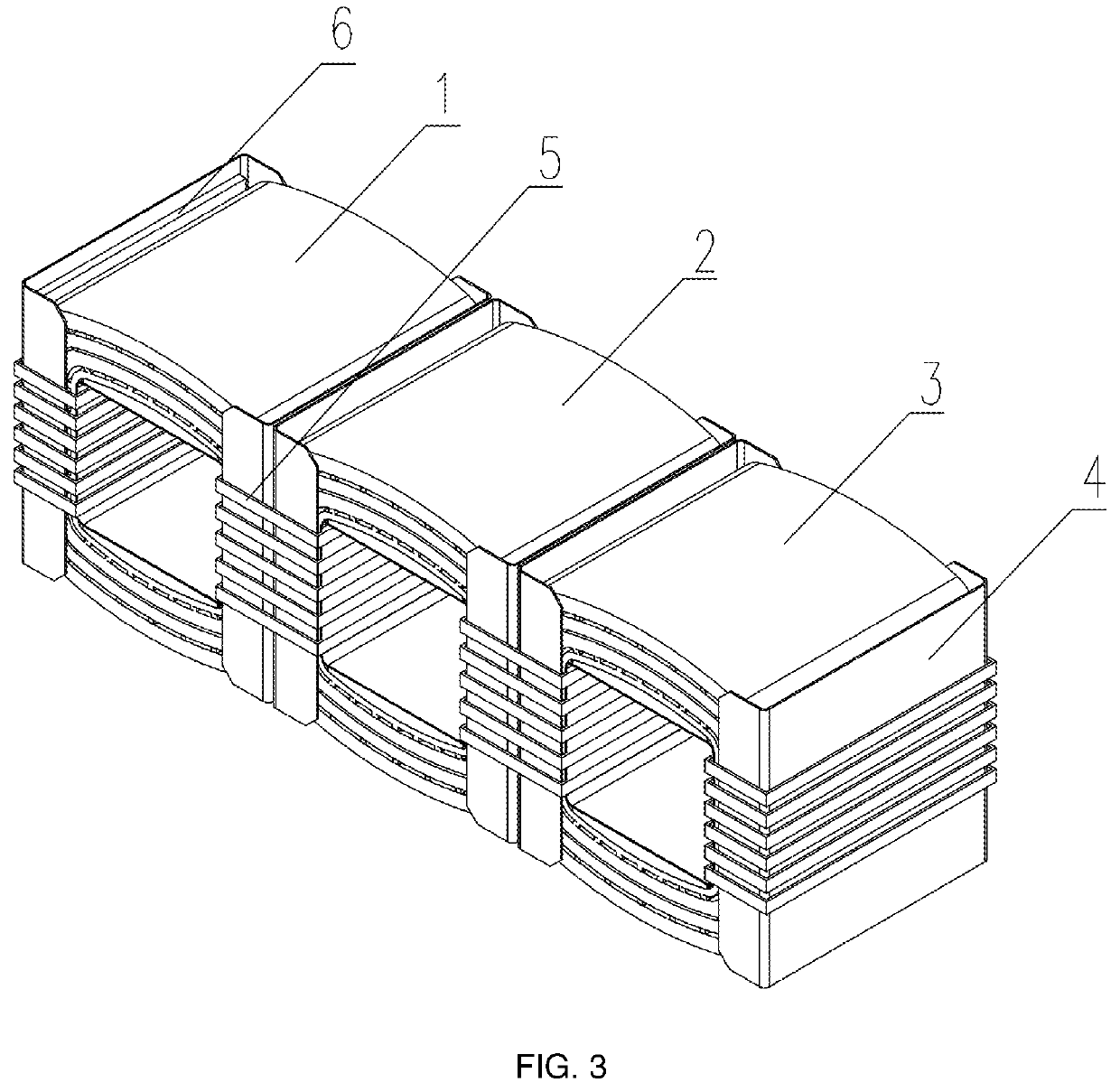
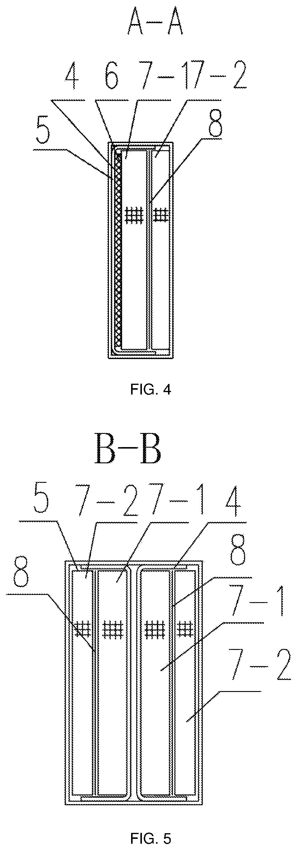
[0020]As shown in FIGS. 1 to 3, a self-clamping structure for solving the short-circuit resistance problem of amorphous alloy transformers comprises an A-phase coil, B-phase coil and C-phase coil which are horizontally arranged, wherein the A-phase coil 1 is adjacent to and in close contact with the B-phase coil 2, and the B-phase coil 2 is adjacent to and in close contact with the C-phase coil 3. In FIG. 1, he A-phase coil, the B-phase coil and the C-phase coil each comprise a high-voltage coil located at an outer side thereof and a low-voltage coil located at an inner side thereof; the low-voltage coil is a foil-wound coil formed by winding co...


PUM

PropertyMeasurementUnit
short-circuit resistanceaaaaaaaaaa
mechanical strengthaaaaaaaaaa
voltageaaaaaaaaaa

Abstract

A self-clamping structure for solving a short-circuit resistance problem of amorphous alloy transformers comprises an A-phase coil, a B-phase coil and a C-phase coil which are horizontally arranged, the A-phase coil being in close contact with the B-phase coil, and the B-phase coil being in close contact with the C-phase coil. By using a solidified low-voltage coil as a fastening splint and binding with a high-strength binding strap, the low-voltage coils of the A-phase and the B-phase clamp and fix a weak portion between the A and B phases; and the low-voltage coil of the B-phase and the C-phase clamp and fix a weak portion between the B and C phases. Outer sides of the A- and C-phase coils are each provided with a high-strength insulation splint, so that the splint and the low-voltage coil of corresponding phase constitute the splint pair to clamp and fix the corresponding weak portion.

Description

TECHNICAL FIELD[0001]The present disclosure relates to the field of transformers, and in particular to a self-clamping structure for solving the short-circuit resistance problem (the problem of resisting short circuit) of amorphous alloy transformers.BACKGROUND ART[0002]A coil of an amorphous alloy transformer is mainly composed of a high-voltage coil, a low-voltage coil, an insulator and so on, and the high- and low-voltage coils of the transformer are wound in one piece. Since an iron core of the amorphous transformer is not capable of bearing force and the coil of the amorphous transformer is mostly in a rectangular shape, the low-voltage coil cannot be tightly expanded by the iron core of the amorphous transformer, and a straight-side portion of the rectangular coil has a poor resistance to short circuit. When the transformer is short-circuited, the coil, subjected to actions of an axial force and a radial force, is prone to excessive deformation or short-circuit damage.[0003]At...

Claims


Application Information

Patent Timeline
Patent Type & Authority Patents(United States)
IPC IPC(8): H01F27/30H01F27/28H01F27/32H01F27/40
CPCH01F27/30H01F27/288H01F27/32H01F27/402H01F30/12H01F27/25
Inventor ZHOU, GUOWEIHUANG, YUANBENPENG, GUOJUNZHAO, WENJUN
Owner JIANGSU HUAPENG TRANSFORMER
Why Eureka
Try Eureka