Turbine housing of turbocharger

a turbocharger and turbine housing technology, applied in the field of turbine housings of turbochargers, can solve the problems of generating and propagating cracks, prone to stress concentration of the curved wall portion adjacent to the wastegate valve seat, and so as to achieve the effect of effectively preventing the generation and propagation of cracks

Active Publication Date: 2021-02-02
HONDA MOTOR CO LTD
View PDF3 Cites 0 Cited by
  • Summary
  • Abstract
  • Description
  • Claims
  • Application Information

AI Technical Summary

Benefits of technology

[0006]In view of such a problem of the prior art, a primary object of the present invention is to provide a turbine housing of a turbocharger that can effectively prevent the generation and propagation of cracks without increasing the material cost and / or the weight.

Problems solved by technology

The part of the curved wall portion adjacent to the wastegate valve seat is prone to stress concentration, and cracks are likely to be generated and propagated in this region.

Method used


Image

  • Turbine housing of turbocharger
  • Turbine housing of turbocharger
  • Turbine housing of turbocharger

Examples


Embodiment Construction

)

[0042]A preferred embodiment of the present invention is described in the following with reference to the appended drawings.

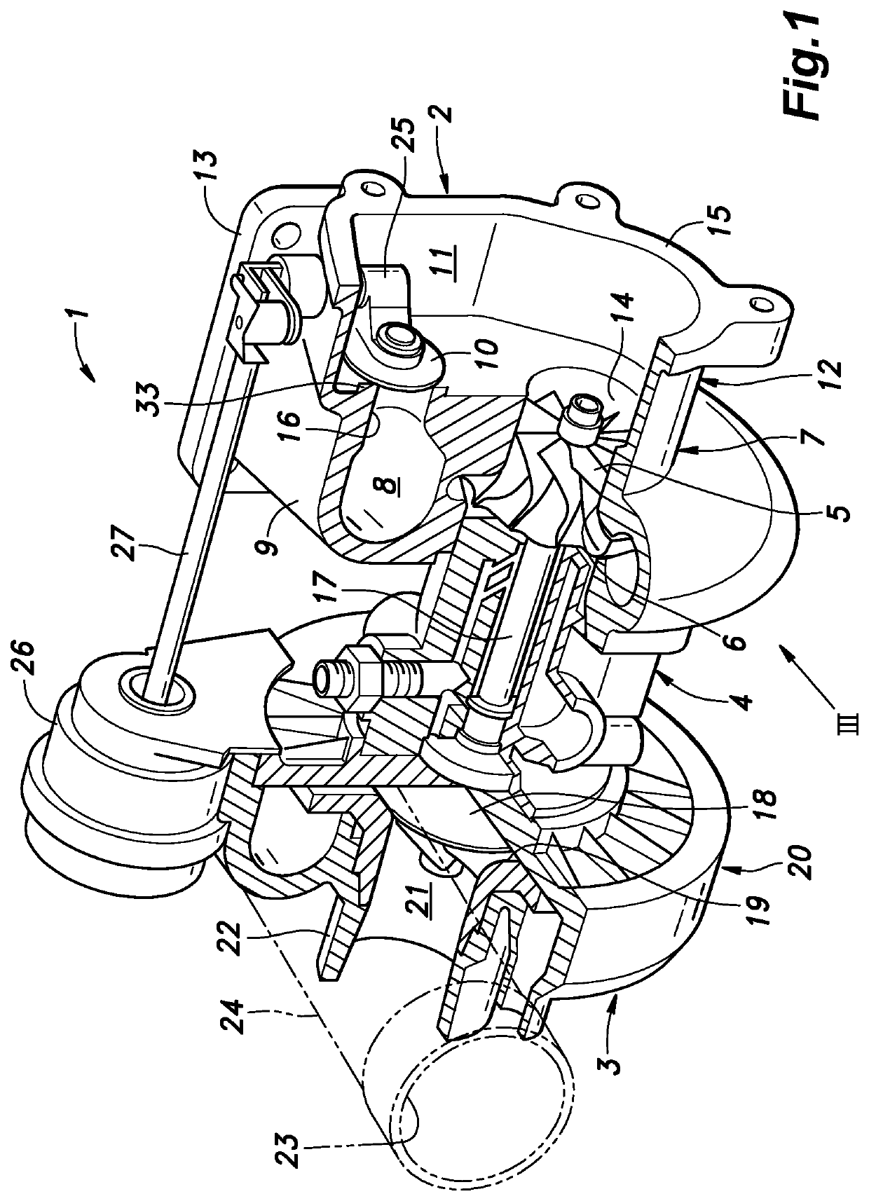
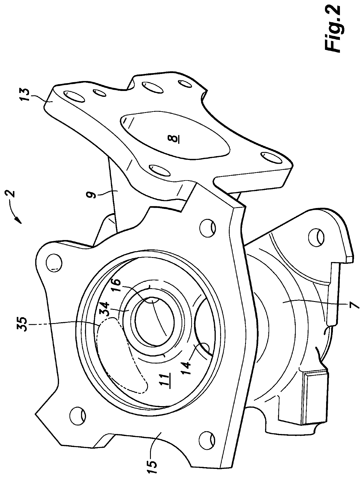
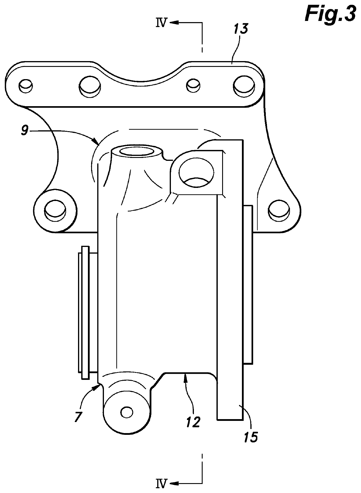
[0043]FIG. 1 is a perspective view of a turbocharger 1 according to an embodiment of the present invention partly in section. As shown in FIG. 1, the turbocharger 1 includes a turbine housing 2, a compressor housing 3, and a center housing 4 (bearing housing) that joins the turbine housing 2 to the compressor housing 3. The turbine housing 2 includes a turbine housing portion 7 that defines a turbine chamber 6 that accommodates a turbine wheel 5, an exhaust inlet passage portion 9 that defines an exhaust inlet passage 8 that communicates with the turbine chamber 6 in a tangential direction, and a valve housing portion 12 that defines a wastegate outlet passage 11 (which also serves as an exhaust outlet passage). The wastegate outlet passage 11 communicates with the exhaust inlet passage 8 via a wastegate valve 10.

[0044]The turbine housing portion 7 receives a ...


PUM


Abstract

In a turbine housing (2) of a turbocharger (1) including a turbine housing portion (7) defining a turbine chamber, an exhaust inlet passage portion 9 (9) defining an exhaust inlet passage, and a valve housing portion (12) defining a wastegate outlet passage (11) communicating with the turbine chamber via a turbine outlet passage (14) and with the exhaust inlet passage via a bypass passage (16), a wastegate valve (10) is pivotally supported by the valve housing portion to cooperate with a wastegate valve seat (34) provided at a downstream end of the bypass passage. A valve peripheral wall portion (33) of the valve housing portion includes a curved wall portion (32), and a part of the curved wall portion adjacent to the wastegate valve seat is formed with a thick wall portion (35) having a locally increased thickness.

Description

TECHNICAL FIELD[0001]The present invention relates to a turbine housing of a turbocharger.BACKGROUND ART[0002]The turbocharger is known as a device for increasing the output of an internal combustion engine by compressing the intake of the engine by making use of the energy of the engine exhaust gas. The housing of the turbocharger typically consists of a turbine housing, a compressor housing and a center housing or a bearing housing that integrally joins the compressor housing and the turbine housing to each other. A bearing shaft extends through the center housing, and connects a turbine wheel received in a turbine chamber defined in the turbine housing to a compressor wheel received in a compressor chamber defined in the compressor housing. The rotational power of the turbine wheel generated by the flow of the exhaust gas is transmitted, via the bearing shaft, to the compressor wheel which compresses the intake of the engine.[0003]The turbocharger is typically provided with a byp...

Claims


Application Information

Patent Timeline
Patent Type & Authority Patents(United States)
IPC IPC(8): F02B37/18F02C6/12
CPCF02B37/183F02C6/12F05D2220/40F01D25/24F02B39/00Y02T10/12
Inventor SANO, TOSHIKAZU
Owner HONDA MOTOR CO LTD
Why Eureka
Try Eureka