
Fountain light

a technology of mountain light and light source, which is applied in the field of lamps, can solve the problems that the mountain system cannot be used in household applications or parties, and achieve the effect of gentle light and clear sigh

Active Publication Date: 2021-02-02
FUJIAN QUANZHOU FANTA CRAFTS CO LTD
View PDF10 Cites 1 Cited by
  • Summary
  • Abstract
  • Description
  • Claims
  • Application Information

AI Technical Summary

Benefits of technology

The present invention is about a fountain light that can be easily moved to different places with limited space. The goal is to provide a flexible and efficient solution for creating a fountain light that can transform into different forms.

Problems solved by technology

The above fountain lights are widely used in various public places, The fountain lights must cooperate with the fountain system in site in order to achieve the effect of lighting fountain, but the fountain system itself is not easy to transfer and requires a certain degree of accommodation space, which results in that the fountain system cannot be used in household application or a party without large square.

Method used


Image

  • Fountain light
  • Fountain light
  • Fountain light

Examples


embodiment 1

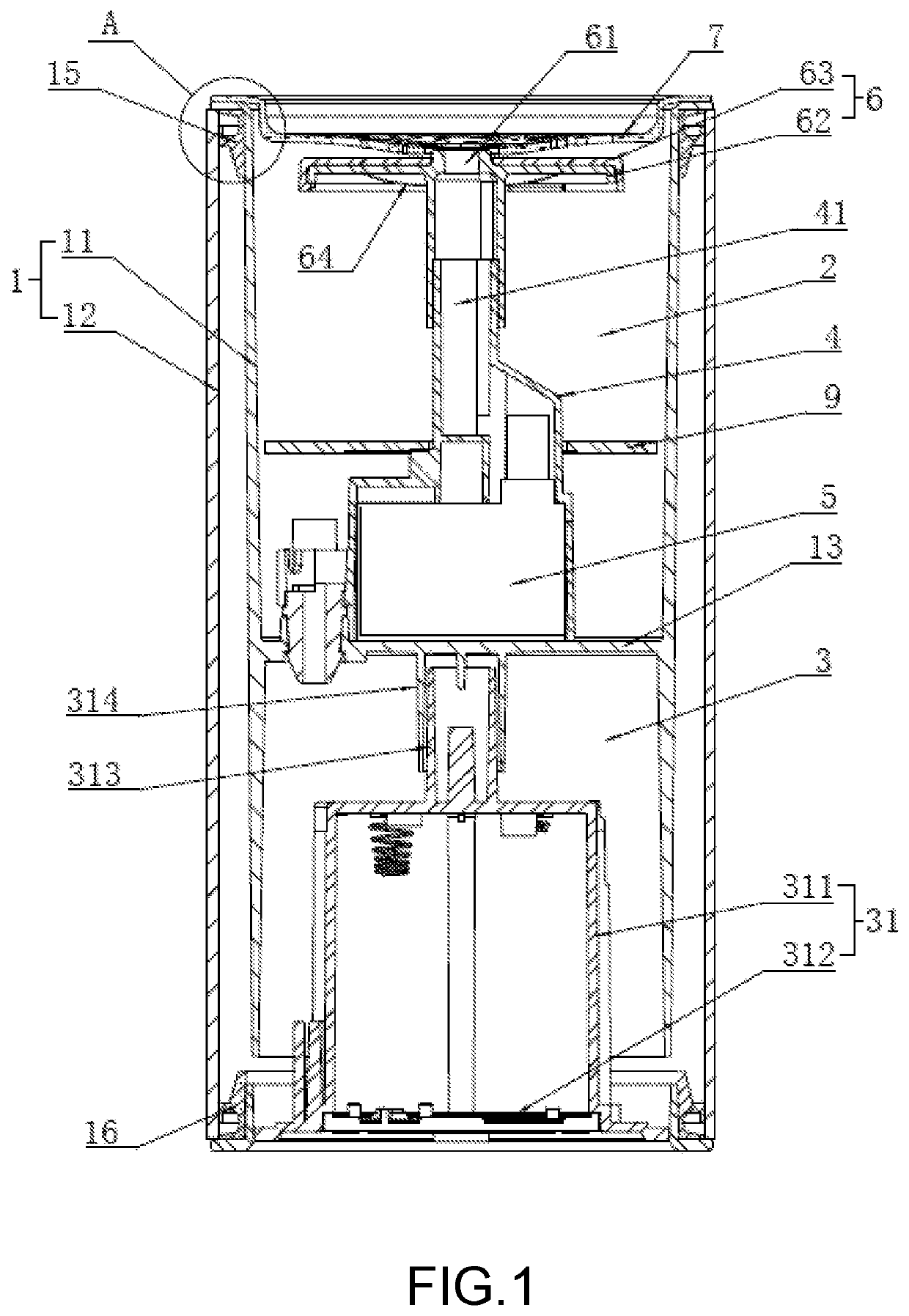
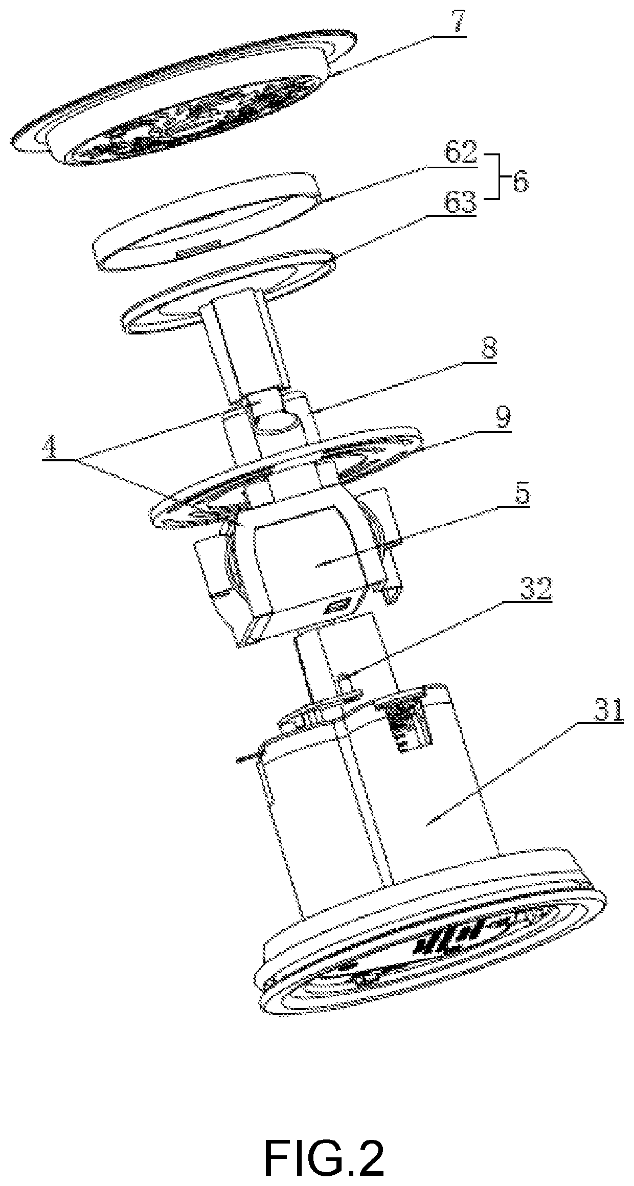
[0044]In embodiment 1, referring to FIGS. 1 and 2, a fountain light disclosed by the present invention comprises a hollow cylindrical light body 1, in which an isolation plate 13 is fixed for dividing the inner chamber of the light body 1 into a water storage chamber 2 and a power supply chamber 3, which are vertically arranged one above the other. The water storage chamber 2 can store water therein, accommodate a light and a fountain forming structure. The power supply 3 contains a power supply 31 and a control chip therein, so as to supply power to members in the water storage chamber 2 and control the light and the fountain to turn on / off.

[0045]The water storage chamber 2 is provided with a water-passing bracket 4 and a pump 5 at the bottom thereof. The pump 5, which can be a low-voltage DC pump, is mounted in the water-passing bracket 4. The water-passing bracket 4 is provided therein with a water passage 41 communicated with the water outlet of the pump 5. A light permeable lig...

embodiment 2

[0053]Regarding embodiment 2, referring to FIG. 6, the differences between embodiments 1 and 2 lie in the following aspects. Four water outlet holes 61 are arranged in the light hood 6. The water-passing bracket 4 comprises a main body 42, a shunt disc 43 and nozzles 44, which are sequentially interconnected from below to above. The nozzle 44 is arranged to communicate with the water outlet hole 61, and the number of the nozzles 44 corresponds to the number of the water outlet holes 61. The nozzles 44 are inclined with respect to the central axis of the inner cavity of the light body 1, and the extension lines of the upper ends of the nozzles 44 converge at the central axis of the light hood 6. The light hood 6 is provided with a supporting tube 65 at the convex part of the bottom thereof. The shunt disc 43 is provided with a supporting base 45 at the convex part of the top thereof for mounting the supporting tube 65.

[0054]The water-passing passage 41 comprises a main passage 421, s...

embodiment 3

[0056]Regarding embodiment 3, referring to FIG. 7, the difference between embodiments 3 and 2 lies in the following aspect. The extension lines of the lower ends of the nozzles 44 converge at the central axis of the light hood 6.


PUM


Abstract

The invention relates to a fountain light comprising a light body. The light body is provided therein with an isolation plate dividing an inner chamber of the light body into a water storage camber and a power supply chamber, which are vertically arranged one above the other. The concaved part of the decorative cover has a hollowed-out pattern. The lighting fountain can be integrated into a small sized lamp, which has the effect that it can be flexibly transferred to various sites where the available space is limited.

Description

CROSS-REFERENCE TO RELATED APPLICATION[0001]This application claims the priority benefit of China application No. 201921932563.9, filed on Nov. 11, 2019. The entirety of the above-mentioned patent application is hereby incorporated by reference herein and made a part of this specification.TECHNICAL FIELD[0002]The present invention relates to a technical field of lamp, in particular to a fountain light.BACKGROUND ART[0003]A lighting fountain is an assembly for spraying water or other liquid under pressure through sprinkler to form specific patterns, which has the effect of decontaminating the air and beautifying the environment. The fountain lights are commonly used in a lighting fountain to illuminate the fountain. There are two kinds of conventional fountain light, one of which is installed under water in the fountain pool, and the other of which is mounted directly on the ground of the square. For example, the Chinese patent NO. “CN204005531U” discloses an LED fountain light. In t...

Claims


Application Information

Patent Timeline
Patent Type & Authority Patents(United States)
IPC IPC(8): F21V33/00F21V23/02F21V3/02B05B17/08F21V31/00F21S10/00F21W121/02
CPCF21V33/006B05B17/08F21S10/002F21V3/02F21V23/023F21V31/005F21W2121/02F21Y2105/10
Inventor HE, KE
Owner FUJIAN QUANZHOU FANTA CRAFTS CO LTD
Learn More