Calibration device of on-board radar

a calibration device and radar technology, applied in the direction of measurement devices, using reradiation, instruments, etc., can solve the problems of increasing the complexity of the radar calibration operation, increasing the difficulty of locating and increasing the quantity of the radar calibration auxiliary device. , the effect of reducing the number of elements of the radar calibration auxiliary devi

Active Publication Date: 2021-02-16
AUTEL INTELLIGENT TECHNOLOGY CORP LTD
View PDF53 Cites 23 Cited by
  • Summary
  • Abstract
  • Description
  • Claims
  • Application Information

AI Technical Summary

Benefits of technology

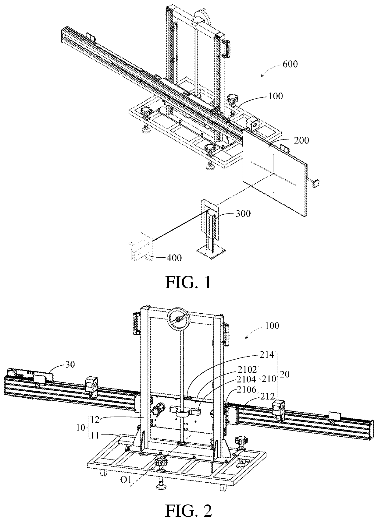
[0005]In order to resolve the foregoing technical problem, embodiments of the present invention provide an on-board radar calibration device for facilitating a calibration operation.
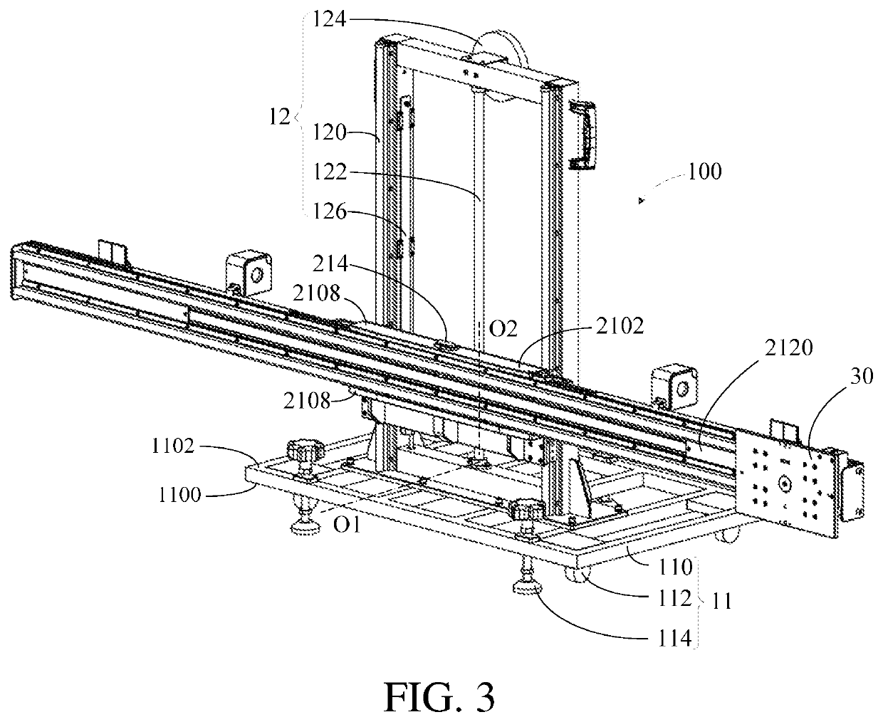
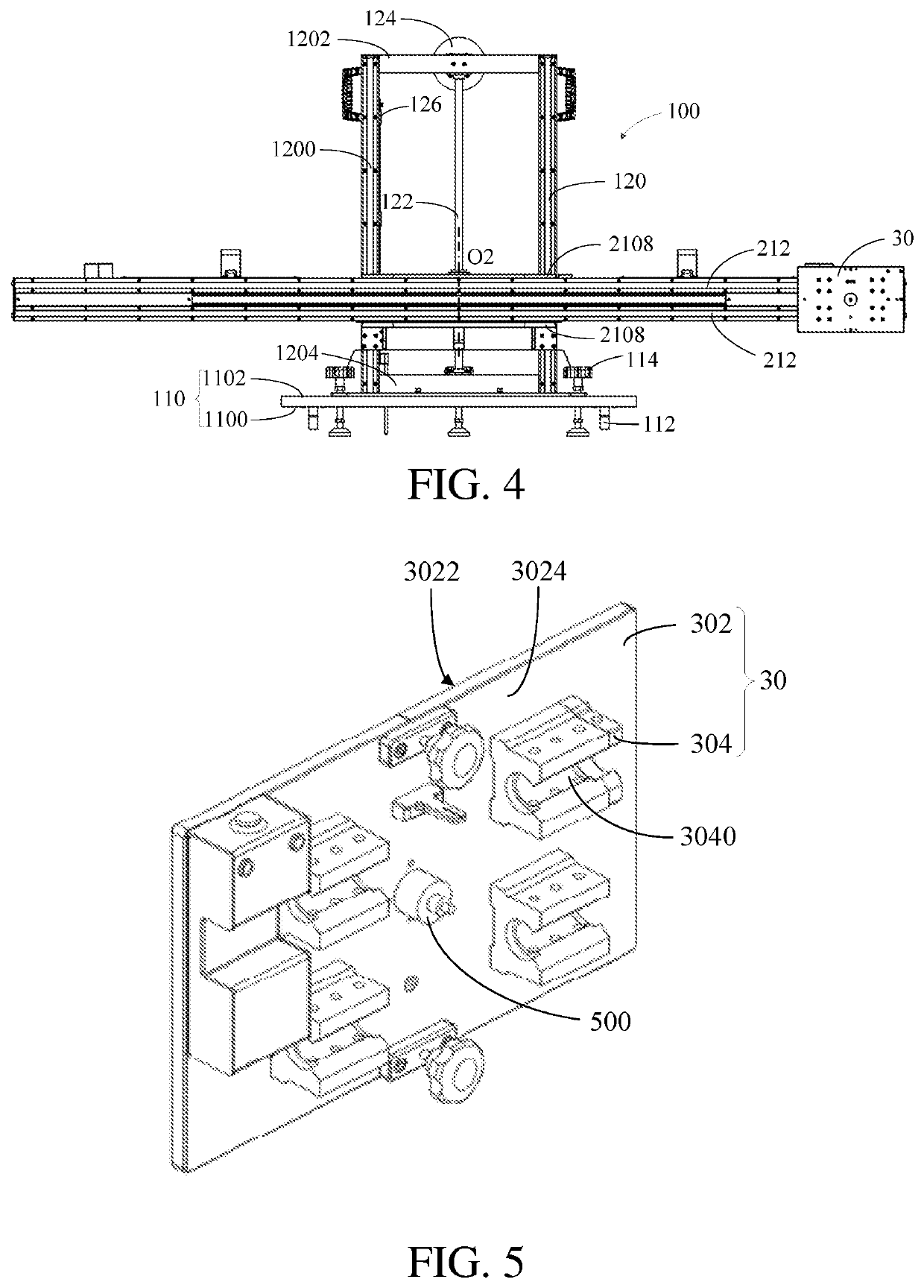
[0064]In comparison with the prior art, the calibration laser is mounted on the second surface, and the calibration laser is partially accommodated in the mounting through hole, so that the calibration laser can horizontally slide in synchronization with the sliding member, thereby facilitating positioning of radar calibration auxiliary devices of different automobile models to calibrate on-board radars of different automobile models.
[0065]In addition, the calibration of the vertical plane of the radar calibration auxiliary device may be implemented by using the radar calibration auxiliary device, the diaphragm, and the laser. The radar calibration auxiliary device may be used for both the calibration of the vertical plane and positioning of the radar calibration auxiliary device. In this way, a quantity of elements of the radar calibration auxiliary device is reduced, costs are reduced, and a calibration operation is simplified.

Problems solved by technology

The mounting position and the mounting angle may change due to uncontrollable factors such as vibration and collision caused of the automobile.
This increases difficulty of locating the radar calibration auxiliary device and increases complexity of a radar calibration operation.

Method used


Image

  • Calibration device of on-board radar
  • Calibration device of on-board radar
  • Calibration device of on-board radar

Examples


Embodiment Construction

[0079]For ease of understanding the present invention, the present invention is described in further detail below with reference to the accompanying drawings and specific embodiments. It should be noted that an element described as being “fixed” to another element may be directly on the other element, or one or more intervening components may be present. An element described as being “connected” to another element may be directly connected to the other element, or one or more intervening components may be present. The terms “vertical”, “horizontal”, “left”, “right”, “inside”, “outside”, and similar expressions, as used in this specification, are for the purpose of description only.

[0080]Unless otherwise defined, all technical and scientific terms used herein have the same meaning as commonly understood by one of ordinary skill in the art to which the present invention belongs. In this specification, terms used in the specification of the present invention are merely intended to desc...


PUM


Abstract

The present application relates to the field of automobile maintenance and device calibration, and discloses an on-board radar calibration device. The on-board radar calibration device includes a bracket assembly, a beam assembly, a sliding member, and a calibration laser. The beam assembly is mounted on the bracket assembly, and is movable relative to the bracket assembly in a vertical direction. The sliding member is mounted on the beam assembly and is movable relative to the beam assembly in a horizontal direction, the sliding member including a first surface and a second surface opposite to each other and being provided with a mounting through hole, and the mounting through hole penetrating the first surface and the second surface. The calibration laser is accommodated in the mounting through hole and is configured to emit a laser beam toward a to-be-calibrated automobile. In the present application, the calibration laser can horizontally slide in synchronization with the sliding member, thereby facilitating positioning of radar calibration auxiliary devices of different automobile models to calibrate on-board radars of different automobile models.

Description

[0001]The present application is a continuation of International Patent No. PCT / CN2019 / 077147 filed on Mar. 6, 2019, which claims priority to Chinese Patent Application No. 201810187748.5 filed on Mar. 7, 2018, both of which are incorporated herein by reference in their entireties.BACKGROUNDTechnical Field[0002]The present application relates to the technical field of automobile maintenance and device calibration, and in particular, to an on-board radar calibration device.Related Art[0003]In the field of advanced driver assistant systems (ADAS), an adaptive cruise control (ACC) system is a commonly used auxiliary function. A specific working principle of the ACC system is that a distance between an automobile and a preceding automobile is measured in real time by using an on-board radar, a speed of the automobile is compared with that of the preceding automobile, and power systems such as an accelerator and a brake of the automobile are controlled, so that the automobile always main...

Claims


Application Information

Patent Timeline
Patent Type & Authority Patents(United States)
IPC IPC(8): G01S7/40
CPCG01S7/4026G01S7/40G01S7/4017G01S2007/403G01S7/4052G01S13/931G01S7/4086G01S7/403
Inventor TANG, XINGUANGWANG, XIAOLONG
Owner AUTEL INTELLIGENT TECHNOLOGY CORP LTD
Why Eureka
Try Eureka