
Tool head and glass or glass ceramic article producible using the tool head

a tool head and tool head technology, applied in the direction of stone-like material working apparatus, instruments, transportation and packaging, etc., can solve the problems of only suitable drills, risk of crack formation, and inability to mill, so as to reduce the vibration of the head, reduce the diameter of the tool head, and reduce the effect of knocking

Active Publication Date: 2021-02-23
SCHOTT AG
View PDF65 Cites 0 Cited by
  • Summary
  • Abstract
  • Description
  • Claims
  • Application Information

AI Technical Summary

Benefits of technology

The patent describes a milling tool that can drill recesses without moving the tool laterally. The design of the tool allows for smooth walls and less vibration and knocking. The tool can also be used for drilling without any movement of the tool head, which ensures very smooth walls. This design maximizes the diameter of the tool head relative to the recess and ensures that material is removed from the entire surface area swept by the tool.

Problems solved by technology

However, with a drill of this type with material removing operation there is a risk of crack formation in case of hard and brittle materials such as glass or glass ceramics.
Moreover, the drill is only suitable for introducing bores, but not for milling.
It has not been possible so far to produce blind holes with diameters and depths that have to be ground using tools with a ratio of tool shank diameter to tool length of smaller than 1:10 in glass ceramics and with a still acceptable reduction in material strength, because of instability of the tool shanks.

Method used


Image

  • Tool head and glass or glass ceramic article producible using the tool head
  • Tool head and glass or glass ceramic article producible using the tool head
  • Tool head and glass or glass ceramic article producible using the tool head

Examples


Embodiment Construction

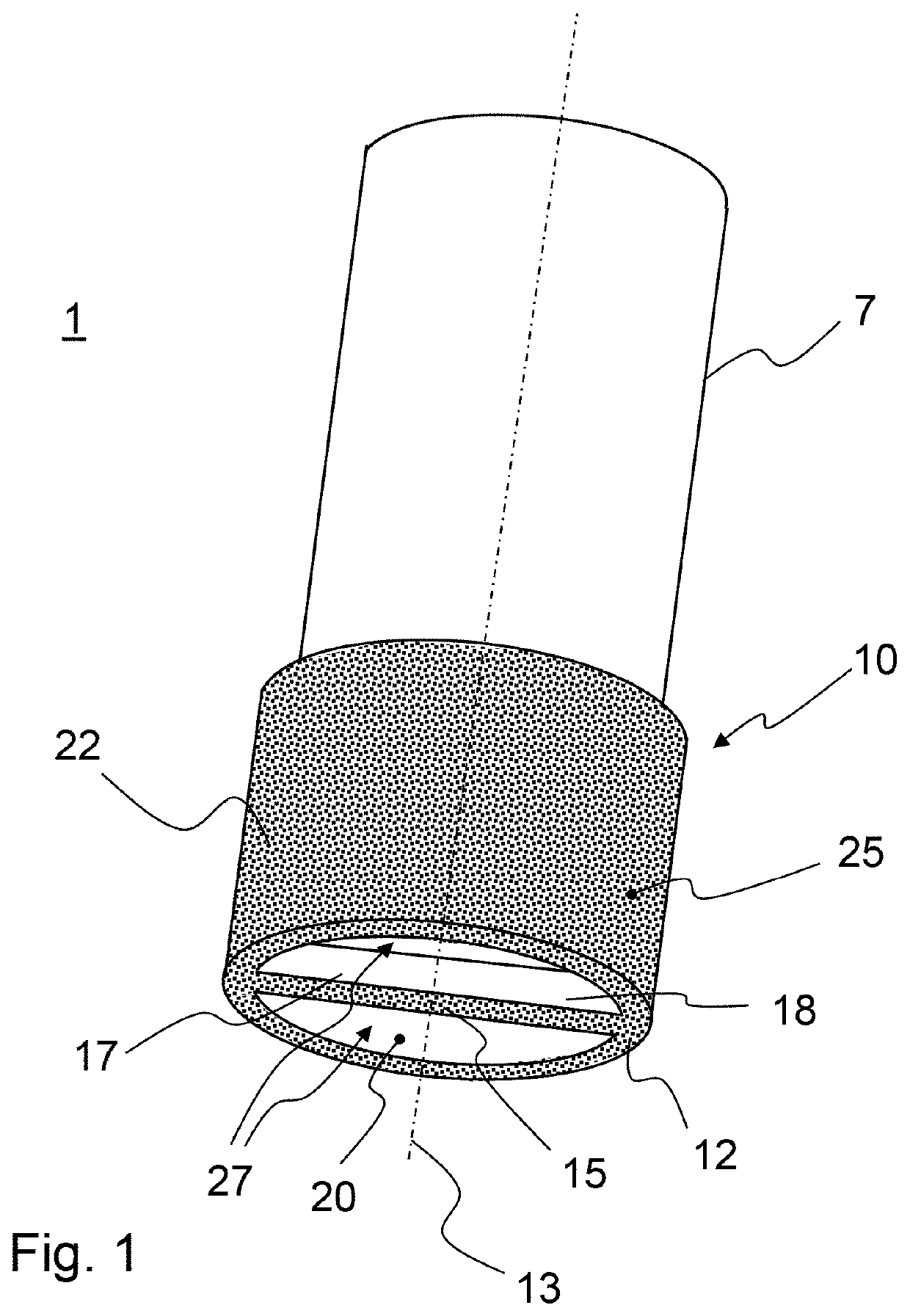
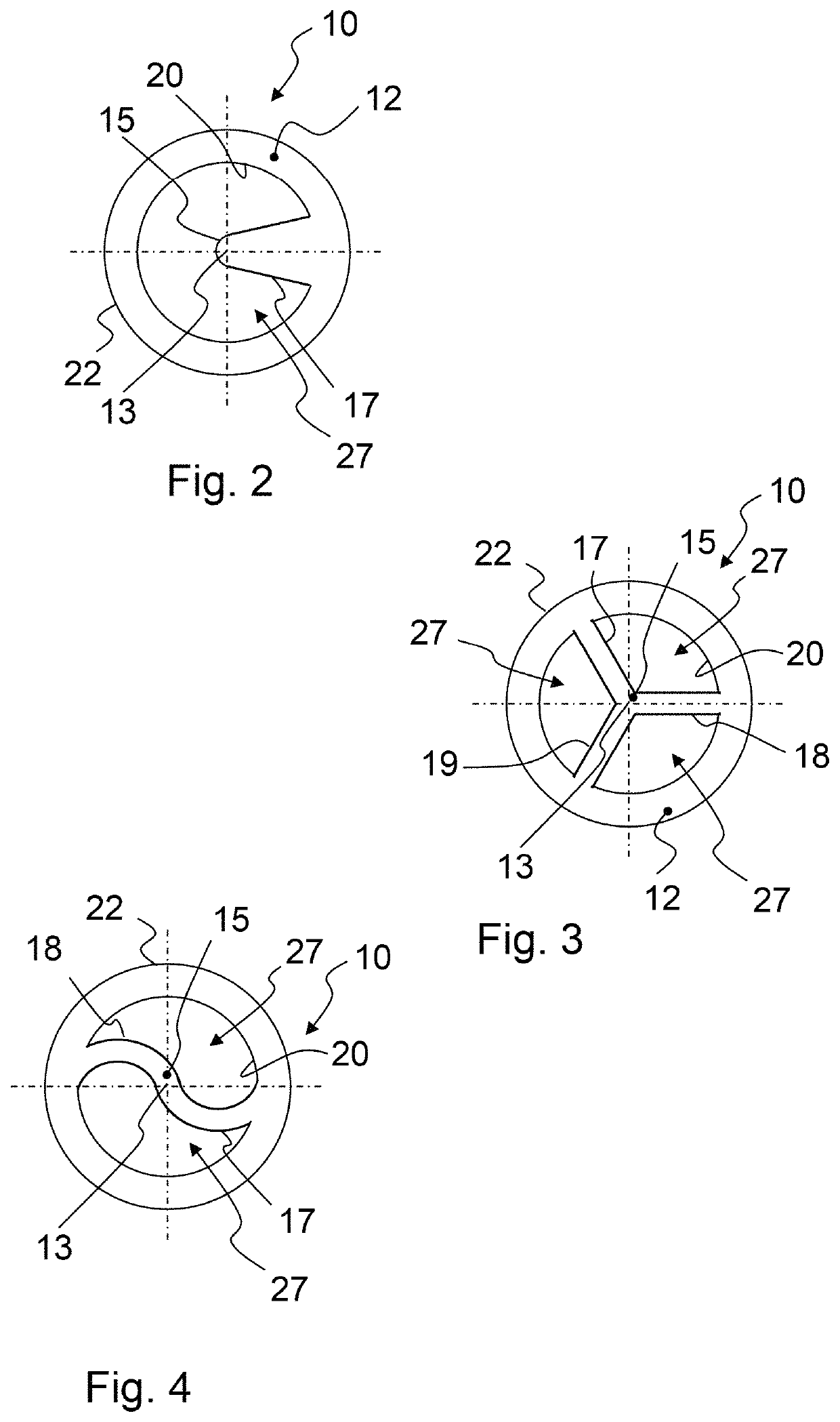
[0030]FIG. 1 shows a perspective view of an exemplary embodiment of a tool head 1 according to the invention.

[0031]Tool head 1 comprises an abrasive body 10 which has the basic shape of a hollow cylinder. Abrasive body 10 merges into a shank 7. That means, the abrasive body 10 may be attached to the shank, or shank and abrasive body 10 are integrally formed, for example turned from a tube of a suitable diameter. Shank 7 also has the shape of a hollow cylinder. Without being limited to the specific embodiment shown in FIG. 1, shank 7 preferably has a smaller diameter than abrasive body 10, in order to facilitate the milling and / or drilling of recesses of a depth greater than the axial length of the abrasive body 10. Generally, without being limited to the specific example shown in FIG. 1, the abrasive body 10 is integrally formed according to one embodiment, in particular as a molded body. To this end, abrasive body 10 including the one or more web(s) may be milled from a metal body,...


PUM

PropertyMeasurementUnit
radiusaaaaaaaaaa
mean roughnessaaaaaaaaaa
distanceaaaaaaaaaa

Abstract

A tool head capable of introducing deep recesses into hard and brittle material such as glass and glass ceramics is provided. The tool head includes a hollow cylindrical abrasive body merging into a hollow shank. The hollow cylindrical abrasive body has an end face with a central abrasive area at the location of a cylinder axis. The central abrasive area is connected with the inner wall surface of the hollow cylindrical abrasive body by at least one web. The end face of the abrasive body, the web, and at least a portion of the outer wall surface of the abrasive body are covered with abrasive. The hollow shank has at least one opening to the interior between the at least one web and the inner wall surface of the abrasive body.

Description

CROSS REFERENCE TO RELATED APPLICATIONS[0001]This application claims benefit under 35 U.S.C. § 119(a) of German Patent Application No. 10 2013 106 612.7, filed Jun. 25, 2013, the entire contents of which are incorporated herein by reference.BACKGROUND OF THE INVENTION[0002]1. Field of the Invention[0003]The invention generally relates to rotary material removing tools. More particularly, the invention relates to a rotary machining tool head, especially for introducing recesses into glass or glass ceramics.[0004]2. Description of the Related Art[0005]From DE 35 34 426 C1 a drilling device is known for drilling plates susceptible to breaking, in particular glass plates. The plate to be drilled is fixed by a support and a holding down member. Support and holding down member are formed by inner rings of ball joint bearings in order to prevent bending stresses when fixing the glass plate. A hole is produced using two counteracting hollow drills that are movable towards each other.[0006]F...

Claims


Application Information

Patent Timeline
Patent Type & Authority Patents(United States)
IPC IPC(8): G02B7/00B28D1/14B28D1/18B28D1/04B24D7/14
CPCB28D1/146B24D7/14B28D1/041B28D1/186G02B7/00Y10T428/24355Y10T428/24479
Inventor MISCHKE, STEFANWERNER, THOMASWEISENBURGER, MARCO
Owner SCHOTT AG
Learn More