Vascular valve prosthesis

a prosthetic valve and valve valve technology, applied in the field of medical devices, can solve the problems of inability to function properly of the valve, venous disease due to incompetent venous valves, and prone to failure of the prosthetic membrane or flap valve, so as to prevent the backflow of blood through the valve, facilitate blood flow, and minimize the diameter of the delivery catheter

Active Publication Date: 2021-02-09
INNOVEIN INC
View PDF55 Cites 1 Cited by
  • Summary
  • Abstract
  • Description
  • Claims
  • Application Information

AI Technical Summary

Benefits of technology

[0009]The vascular valve prosthesis systems described herein generally include a delivery catheter. During placement of an implantable vascular valve prosthesis, it is desirable to minimize the diameter of the delivery catheter used to deploy the valve, to facilitate intravenous access and prosthesis insertion. A smaller diameter delivery catheter is desirable, because it may be inserted into a vein using a smaller puncture hole, and because it decreases trauma to the venous endothelium during advancement and manipulation of the catheter. On the other hand, it is desirable to maximize the diameter of the ball used in the venous valve, as a larger diameter ball may be paired with a valve seat containing a larger diameter valve orifice, to decrease flow resistance through the valve. Enhancing flow characteristics through the valve is important, in order to avoid thrombus (clot) formation in the valve, which may cause valve occlusion. According to various embodiments, the ball within the prosthetic valve may be collapsible / expandable (or “non-rigid”), so that it will change from a smaller diameter configuration during delivery to a larger diameter configuration following implantation. Other embodiments include different or additional mechanisms for preventing clot formation, as will be described further below.
[0010]In one aspect of the present application, a venous valve prosthetic implant for treating a vein includes a tubular, expandable anchoring frame, a valve seat formed at or near the middle of the anchoring frame, an expandable ball disposed within the lumen of the anchoring frame, and a ball retention tether attached to the expandable ball and to the valve seat and / or the anchoring frame. The anchoring member may be a stent that extends from a proximal end to a distal end of the implant and forms a lumen from the proximal end to the distal end. The anchoring frame may include a cylindrical proximal portion at the proximal end, a cylindrical distal portion at the distal end, an inwardly angled inlet portion between the cylindrical proximal portion and a middle of the anchoring frame, and an inwardly angled outlet portion between the cylindrical distal portion and the middle of the anchoring frame. The expandable ball expands from a compressed configuration for delivery into the vein through a delivery catheter to an expanded configuration outside the delivery catheter. The expandable ball in the expanded configuration moves between an open position, in which the expandable ball is located apart from the valve seat, to allow forward flow of blood through the implant, and a closed position, in which the expandable ball contacts the valve seat to prevent backflow of blood through the implant.
[0012]In some embodiments, the expandable ball is a solid, compressible foam ball. Such embodiments may optionally further include at least one weight embedded within the ball. Alternatively, the expandable ball may include an elastic shell and a filler substance inside the elastic shell. For example, the filler substance may be air, a gel or a fluid. Some embodiments include at least one weight inside the elastic shell. Optionally, the filler substance may be a curable substance that hardens when cured. In some embodiments, the filler substance is a spiral-cut, elastic, hollow sphere. In some embodiments, the expandable ball includes an aperture through which the ball retention tether is passed. In some embodiments, the expandable ball has a density of less than 2.5 grams per square centimeter. the ball retention tether is attached to the valve seat, wherein the tether and the valve seat form a filling lumen, and wherein the valve seat is accessible through a filling port to pass a filler substance through the valve seat and the tether to fill the expandable ball. In some embodiments, the expandable ball has a density of no greater than 1.06 grams per square centimeter, and the tether is elastic, to pull the ball toward the valve seat to prevent backflow of blood through the implant.
[0017]In another aspect of the present disclosure, a method for implanting a venous valve prosthetic implant in a vein or other blood vessel first involves advancing a delivery catheter containing the implant into the vein. The method next involves retracting a catheter body of the delivery catheter and / or advancing a deployment plunger of the delivery catheter, to cause the implant to exit a distal end of the delivery catheter. Then, a tubular stent anchoring member and a ball disposed inside the anchoring member are expanded, within the vein and outside of the delivery catheter. The anchoring member, when expanded, contacts an inner wall of the vein to maintain the implant within the vein. The ball, when expanded, moves between an open position, in which the ball is positioned to allow forward flow of blood through the implant, and a closed position, in which the ball contacts a valve seat, to prevent backflow of blood through the implant. Lastly, the method involves removing the delivery catheter from the vein.

Problems solved by technology

When these valves become compromised, the veins cannot function properly.
Venous disease due to incompetent venous valves is a prevalent clinical problem.
Prosthetic membrane or flap valves are prone to failure, due to tearing from repeated opening and closing of the leaflets, permanent closure due to thrombosis and cell adhesion to the prosthetic leaflets, or leaflet inversion and incompetence over time.
Currently available replacement venous valves, whether artificial or transplanted tissue valves, also often cause problems with thrombosis (clotting) during long term valve implantation.

Method used


Image

  • Vascular valve prosthesis
  • Vascular valve prosthesis
  • Vascular valve prosthesis

Examples


Embodiment Construction

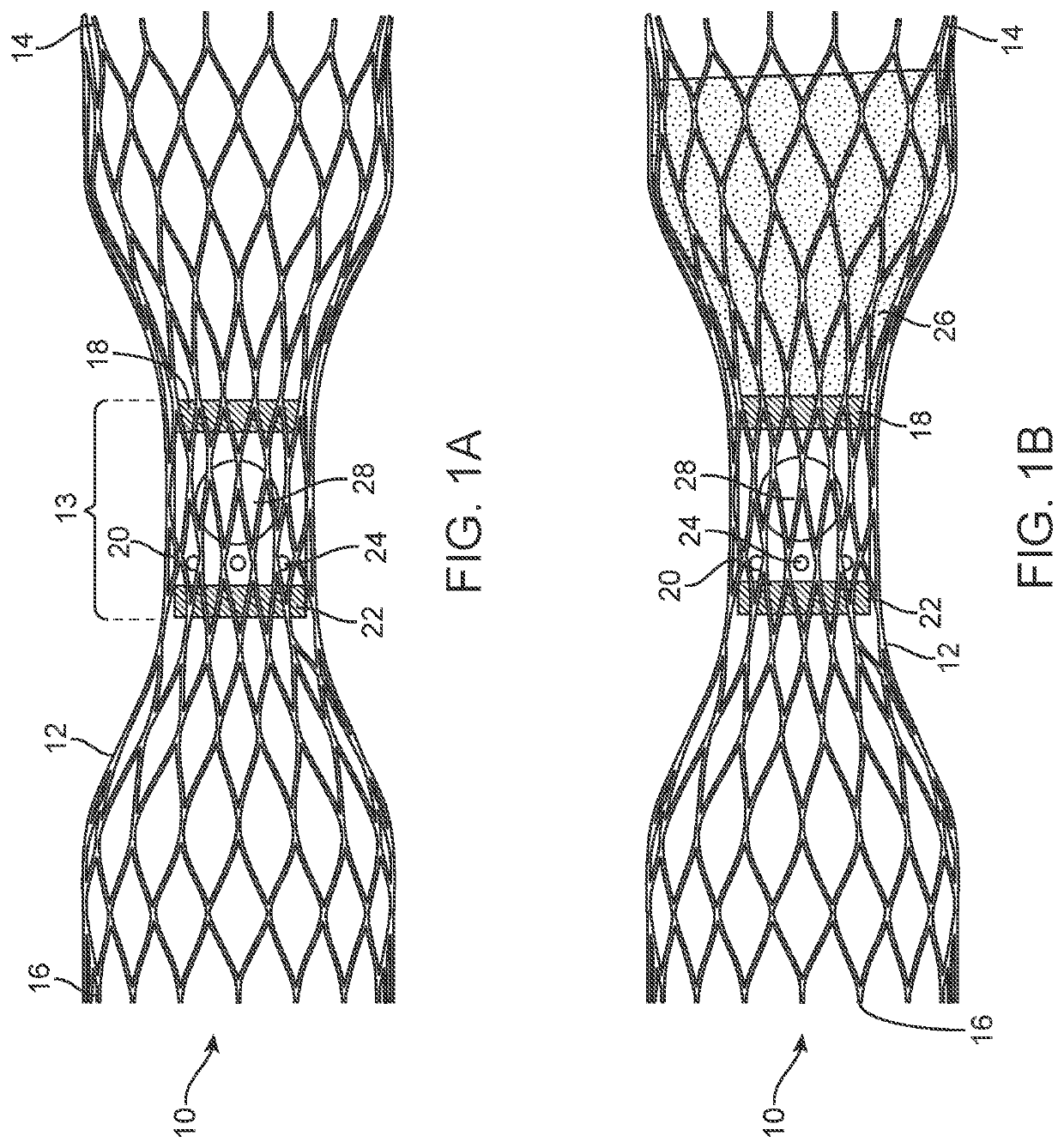
[0068]This application describes various embodiments and features of a device, system, and method involving a vascular valve prosthesis for implantation in a blood vessel to improve function of the blood vessel. In many cases, the vascular valve prosthesis is used in human veins, to help treat venous insufficiency. In alternative embodiments, however, the valve prosthesis may be used in arteries, other locations in the body, such as heart valves or other body lumens, and / or it may be used in animals. Therefore, although the following description focuses on use of the valve prosthesis in veins, this should not be interpreted as limiting the scope of the claims.

[0069]Many of the embodiments described herein are of a vascular ball valve prosthesis, as opposed to prior art leaflet or flap valve approaches. The assignee of the present application described a number of embodiments of ball valve prostheses in U.S. Patent Application Pub. No. 2017 / 0056175, titled “Venous Valve Prosthesis” (...


PUM


Abstract

A valve prosthetic implant for treating a vein or other blood vessel includes a tubular, expandable anchoring frame extending from a proximal end to a distal end of the implant, a valve seat formed at or near the middle of the anchoring frame, an expandable ball disposed within the lumen of the anchoring frame, and a ball retention tether attached to the expandable ball and to the valve seat and / or the anchoring frame. The anchoring frame may include a cylindrical proximal portion at the proximal end, a cylindrical distal portion at the distal end, an inwardly angled inlet portion between the cylindrical proximal portion and a middle of the anchoring frame, and an inwardly angled outlet portion between the cylindrical distal portion and the middle of the anchoring frame.

Description

CROSS-REFERENCE TO RELATED APPLICATIONS[0001]This application is a continuation-in-part of U.S. application Ser. No. 15 / 247,523, filed Aug. 25, 2016, entitled, “VENOUS VALVE PROSTHESIS,” now U.S. Pat. No. 10,231,838, issued Mar. 19, 2019, which claims priority to U.S. Provisional Application Nos. 62 / 209,351, filed Aug. 25, 2015 and 62 / 356,337, filed Jun. 29, 2016, both entitled, “VENOUS VALVE PROSTHESIS.” This application also claims the benefit of U.S. Provisional Patent Application Nos.: 62 / 518,859, filed Jun. 13, 2017, entitled, “VENOUS VALVE PROSTHESIS DEVICE AND METHOD;” and 62 / 610,338, filed Dec. 26, 2017, entitled, “NEUTRAL DENSITY BALL VALVE.” The above-referenced applications are hereby incorporated by reference in their entireties into the present application.TECHNICAL FIELD[0002]This application relates generally to the field of medical devices. More specifically, the application relates to prosthetic valve implant devices, systems and methods for implantation within the ...

Claims


Application Information

Patent Timeline
Patent Type & Authority Patents(United States)
IPC IPC(8): A61F2/24A61F2/06
CPCA61F2/2475A61F2/06A61F2/2424A61F2002/068A61F2230/001A61F2250/0003A61F2250/0096A61F2/2436A61F2210/0014
Inventor CHIN, ALBERT KMOLL, ANDREWKWOK, ANDREWKRAMER, THOMAS AWALKER, AUSTINCHEN, ERIC
Owner INNOVEIN INC
Why Eureka
Try Eureka