Waveguide transition comprising a feed probe coupled to a waveguide section through a waveguide resonator part

a waveguide and resonator technology, applied in the direction of waveguides, electrical devices, coupling devices, etc., can solve the problems of difficult manufacturing of such a transition arrangement, and achieve the effect of robust manufacturing and assembly tolerances

Active Publication Date: 2021-02-23
TELEFON AB LM ERICSSON (PUBL)
View PDF10 Cites 1 Cited by
  • Summary
  • Abstract
  • Description
  • Claims
  • Application Information

AI Technical Summary

Benefits of technology

[0013]A number of advantages are obtained by means of the present invention. Mainly, a transition from a microstrip conductor to a waveguide that is relatively robust regarding manufacture and assembly tole...

Problems solved by technology

However, the higher frequencies that are used, the more difficult it b...

Method used


Image

  • Waveguide transition comprising a feed probe coupled to a waveguide section through a waveguide resonator part
  • Waveguide transition comprising a feed probe coupled to a waveguide section through a waveguide resonator part
  • Waveguide transition comprising a feed probe coupled to a waveguide section through a waveguide resonator part

Examples


Embodiment Construction

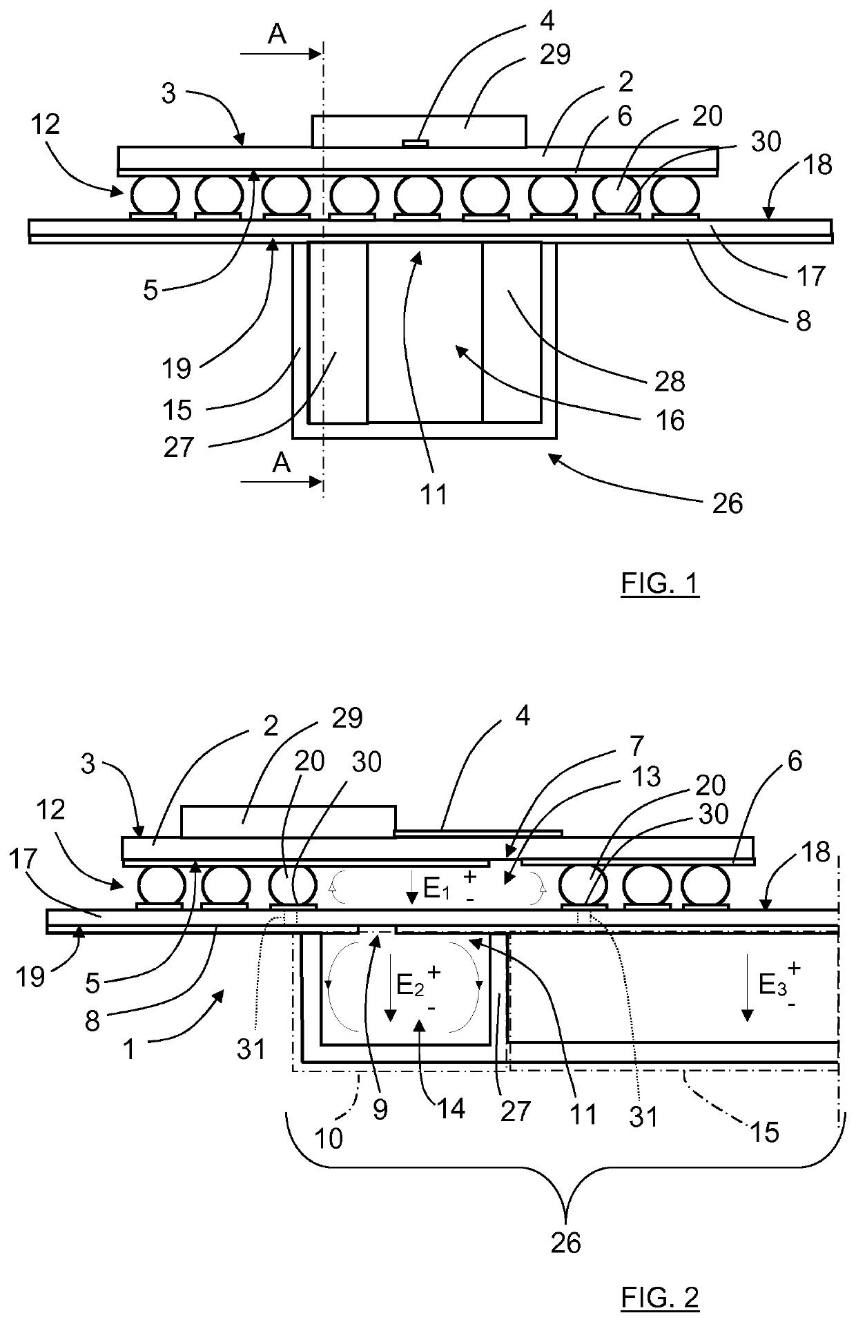
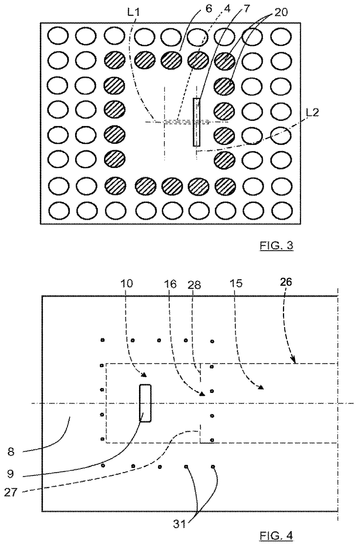
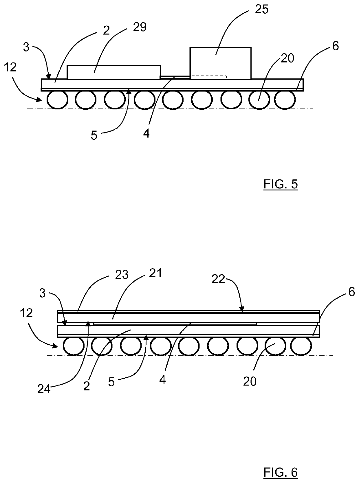
[0025]In the following, reference is made to FIG. 1, FIG. 2, FIG. 3 and FIG. 4. FIG. 1 shows a schematical front view of a waveguide transition arrangement, FIG. 2 shows a schematical cut-open side view of the a waveguide transition arrangement along a line A-A in FIG. 1, FIG. 3 shows a schematical bottom view of a first dielectric layer and FIG. 4 shows a schematical bottom top of a second dielectric layer.

[0026]There is a waveguide transition arrangement 1 (FIG. 2) comprising a first dielectric layer 2 (FIGS. 1 and 2) having a first layer first side 3 (FIGS. 1 and 2) on which a strip conductor 4 (FIGS. 1-3) is positioned and a first layer second side 5 (FIGS. 1 and 2) on which a first ground plane 6 (FIGS. 1-3) with a first aperture 7 (FIGS. 2 and 3) is positioned. The strip conductor 4 has a first longitudinal extension L1 (FIG. 3) and the first aperture has a second longitudinal extension L2 (FIG. 3), and the strip conductor 4 crosses the first aperture 7 such that the longitudi...


PUM


Abstract

The present disclosure relates to a waveguide transition arrangement (1) comprising a first ground plane (6) with a first aperture (7), a feed probe (4) that crosses the first aperture (7), a second ground plane (8) with a second aperture (9), and a waveguide resonator part (10) that has an opening (11) that faces the second aperture (9). The first ground plane (6) faces the second ground plane (8) and is positioned between the feed probe (4) and the second ground plane (8), and the second ground plane (8) faces the waveguide resonator part (10). A wall structure (12) is at least partly arranged between the first ground plane (6) and the second ground plane (8) such that a first cavity (13) is formed in an enclosed volume between them. The first aperture (7) and the second aperture (9) are electromagnetically connected to the first cavity (13), and where the second aperture (9) to a second cavity (14) in the waveguide resonator part (10) which is electromagnetically connected to a waveguide section (15) via a third aperture (16).

Description

TECHNICAL FIELD[0001]The present invention relates to a waveguide transition arrangement comprising a first ground plane with a first aperture, a feed probe that crosses the first aperture, a second ground plane with a second aperture, and a waveguide resonator part that has an opening that faces the second aperture.BACKGROUND[0002]In many fields of communication, a suitable transition from a microstrip conductor to a waveguide is desired. The most common type of such a transition is based on a probe with a metal back short on top of the probe. The probe is then located perpendicular to a rectangular waveguide, and a metal housing encloses the probe such that a metal back short is obtained by means of a housing wall that runs parallel to the probe at a distance of a quarter wavelength from the probe. The wavelength normally corresponds to the center frequency of the frequency band used.[0003]Such a transition arrangement is for example described in EP 1367668 and U.S. Pat. No. 7,276...

Claims


Application Information

Patent Timeline
IPC IPC(8): H01P5/107H01P3/08H01P3/12H01P5/08
CPCH01P5/107H01P3/08H01P3/12H01P5/08
Inventor LIGANDER, PERTAGEMAN, OLA
Owner TELEFON AB LM ERICSSON (PUBL)
Why Eureka
Try Eureka