
Transmission line and flat cable

a technology of transmission line and flat cable, which is applied in the direction of flat/ribbon cables, waveguides, waveguide type devices, etc., can solve the problems of unfavorable signal transmission, unfavorable signal transmission, and possible leakage of signals between transmission lines due to feedback current, so as to achieve the effect of reducing or preventing undesired radiation, small size and significant reduction of undesired radiation

Active Publication Date: 2017-07-06
MURATA MFG CO LTD
View PDF20 Cites 6 Cited by
  • Summary
  • Abstract
  • Description
  • Claims
  • Application Information

AI Technical Summary

Benefits of technology

The present invention provides a transmission line and flat cable that have multiple transmission line parts in a single insulator, which reduces or eliminates interference between the parts.

Problems solved by technology

H04-144301, it is difficult to adjust the impedance of each signal line to a desired impedance.
In other words, leakage of a signal between transmission lines due to a feedback current is likely to occur.
In such a configuration in which an interlayer connection conductor is arranged between adjacent signal lines, however, the following problems may occur.
In a case of using a structure in which the pitch of the interlayer connection conductor arranged between the adjacent signal lines is made rough or a structure in which the interlayer connection conductor is eliminated, unwanted coupling between the signal lines is likely to occur.
On the other hand, if the pitch of the interlayer connection conductor is made fine, the capacitance between the signal line and the interlayer connection conductor becomes larger and a desired characteristic impedance as a transmission line is difficult to be achieved.
As the width of the stacked insulator is smaller, the capacitance that is generated between the interlayer connection conductor and the signal line becomes larger and thus a desired characteristic impedance as a transmission line is difficult to be achieved.

Method used


Image

  • Transmission line and flat cable
  • Transmission line and flat cable
  • Transmission line and flat cable

Examples


first preferred embodiment

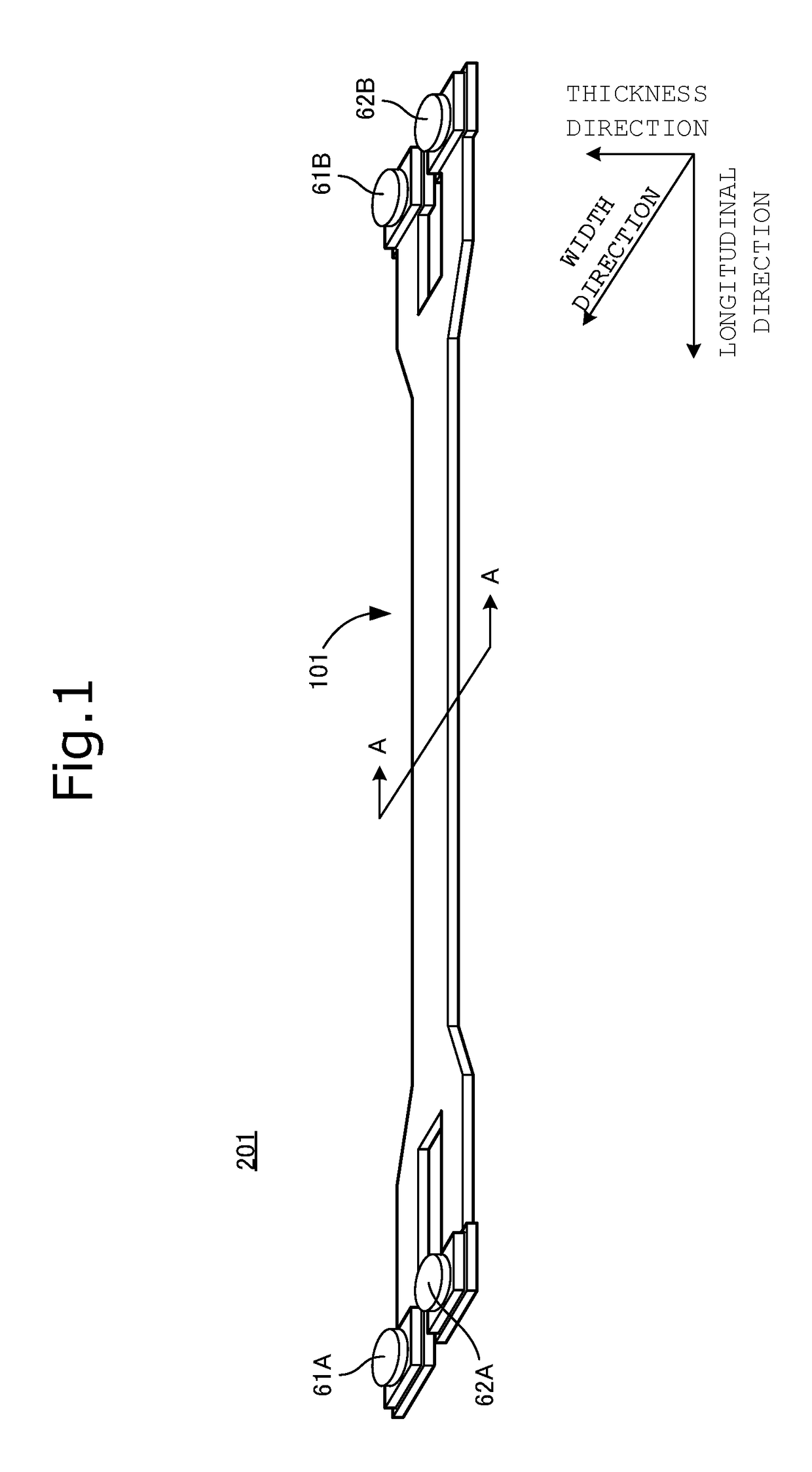
[0035]FIG. 1 is an external perspective view of a flat cable 201 according to a first preferred embodiment of the present invention. The flat cable 201 includes a transmission line 101 and coaxial connectors 61A, 61B, 62A, and 62B mounted on the transmission line 101. The transmission line 101 includes a first transmission line portion and a second transmission line portion. The longitudinal direction of the transmission line 101 is a direction in which a high frequency signal is transmitted. The coaxial connectors 61A and 61B are provided at both ends of the first transmission line portion and the coaxial connectors 62A and 62B are provided at both ends of the second transmission line portion.

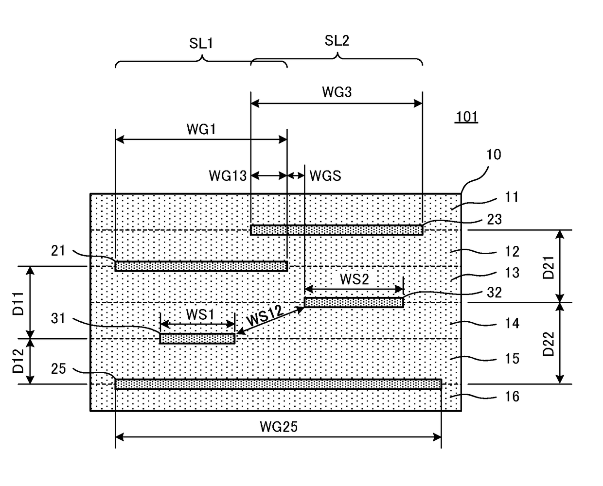
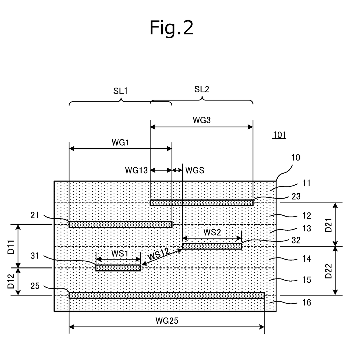
[0036]FIG. 2 is a cross-sectional view of an A-A portion of the transmission line 101 shown in FIG. 1. The transmission line 101 is provided with a stacked insulator 10 in which a plurality of insulator layers 11, 12, 13, 14, 15 and 16 are stacked, and various conductor patterns arranged along...

second preferred embodiment

[0057]FIG. 5 is a cross-sectional view of a transmission line 102 according to a second preferred embodiment of the present invention. Unlike the transmission line 101 described in the first preferred embodiment of the present invention, the transmission line 102 is provided with a second ground conductor pattern 22 and a fourth ground conductor pattern 24. The width WG2 of the second ground conductor pattern 22 is preferably larger than the width WS1 of the first signal conductor pattern 31. In addition, the width WG4 of the fourth ground conductor pattern 24 is preferably larger than the width WS2 of the second signal conductor pattern 32. The first signal conductor pattern 31, in a plan view, overlaps the first ground conductor pattern 21 and the second ground conductor pattern 22 and does not overlap at least one of the third ground conductor pattern 23 and the fourth ground conductor pattern 24. Similarly, the second signal conductor pattern 32, in the plan view, overlaps the t...

third preferred embodiment

[0060]FIG. 6 is a cross-sectional view of a transmission line 103 according to a third preferred embodiment of the present invention. Both the first signal conductor pattern 31 and the second signal conductor pattern 32 of the transmission line 103 are provided on the common insulator layer 14. In addition, the second ground conductor pattern 22 is provided on the insulator layer 15, and the fourth ground conductor pattern 24 is provided on the insulator layer 16. Therefore, the third ground conductor pattern 23 is arranged outside the first ground conductor pattern 21, and the fourth ground conductor pattern 24 is arranged outside the second ground conductor pattern 22. Other features of the transmission line 103 according to the third preferred embodiment are the same or substantially the same as the features of the transmission line 101 described in the first preferred embodiment.

[0061]In the transmission line 103 as shown in FIG. 6, the second ground conductor pattern 22 and the...


PUM

PropertyMeasurementUnit
widthaaaaaaaaaa
distanceaaaaaaaaaa
line widthaaaaaaaaaa

Abstract

A transmission line includes, in a stacked insulator in which insulator layers are stacked, a first transmission line portion including a first ground conductor pattern, a second ground conductor pattern, and a first signal conductor pattern, and a second transmission line portion including a third ground conductor pattern, a fourth ground conductor pattern, and a second signal conductor pattern. The first signal conductor pattern extends along the second signal conductor pattern. The first ground conductor pattern and the third ground conductor pattern are provided on different insulator layers and at least partially overlap each other in a plan view.

Description

CROSS REFERENCE TO RELATED APPLICATIONS[0001]This application claims the benefit of priority to Japanese Patent Application No. 2014-209525 filed on Oct. 10, 2014 and is a Continuation Application of PCT Application No. PCT / JP2015 / 078143 filed on Oct. 5, 2015. The entire contents of each application are hereby incorporated herein by reference.BACKGROUND OF THE INVENTION[0002]1. Field of the Invention[0003]The present invention relates to a transmission line and a flat cable that transmit a plurality of high frequency signals.[0004]2. Description of the Related Art[0005]Various transmission lines that transmit a high frequency signal have been devised. For example, Japanese Patent Laid-Open publication No. H04-144301 discloses a transmission line with a stripline structure. The transmission line disclosed in Japanese Patent Laid-Open publication No. H04-144301 is provided with an elongated stacked insulator that extends in a direction in which a high frequency signal is transmitted, ...

Claims


Application Information

Patent Timeline
Patent Type & Authority Applications(United States)
IPC IPC(8): H01B7/08H01P3/02
CPCH01P3/026H01B7/08H01P3/082H05K1/0219H05K1/0225H05K1/147H05K2201/052H05K2201/10037H05K2201/10189
Inventor YOSUI, KUNIAKIITO, SHINGOKEZUKA, SHUICHIBABA, TAKAHIRO
Owner MURATA MFG CO LTD
Learn More