Slider

a slider and compact technology, applied in the field of sliders, can solve the problems of affecting the the difficulty of maintaining compactness, and the lack of stability of the slider 100

Active Publication Date: 2021-03-02
JUTE INC
View PDF16 Cites 2 Cited by
  • Summary
  • Abstract
  • Description
  • Claims
  • Application Information

AI Technical Summary

Benefits of technology

[0044]With this configuration, a person's part such as hand, knee, toe, and sole can be placed on the stre

Problems solved by technology

However, the stretching slider 100 described in US 2005/0,209,072 (FIGS. 7A and 7B, FIG. 1, paragraphs 38-40, etc.) includes one roller ball 101a, and thus it is difficult to maintain compactness and there has been a problem in terms of lightness as well.
In addition, the stretching slider 100 has been problematic in that the stretching slider 100 lacks stability and whether or not a certain stretching effect can be obtained depends heavily on a user's physical ability such as physical strength.
Accordingly, in a case where a user is a seni

Method used


Image

  • Slider
  • Slider
  • Slider

Examples


first embodiment

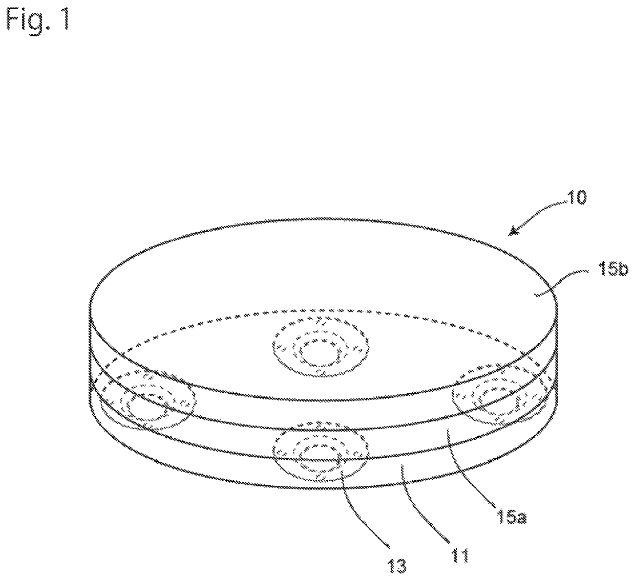
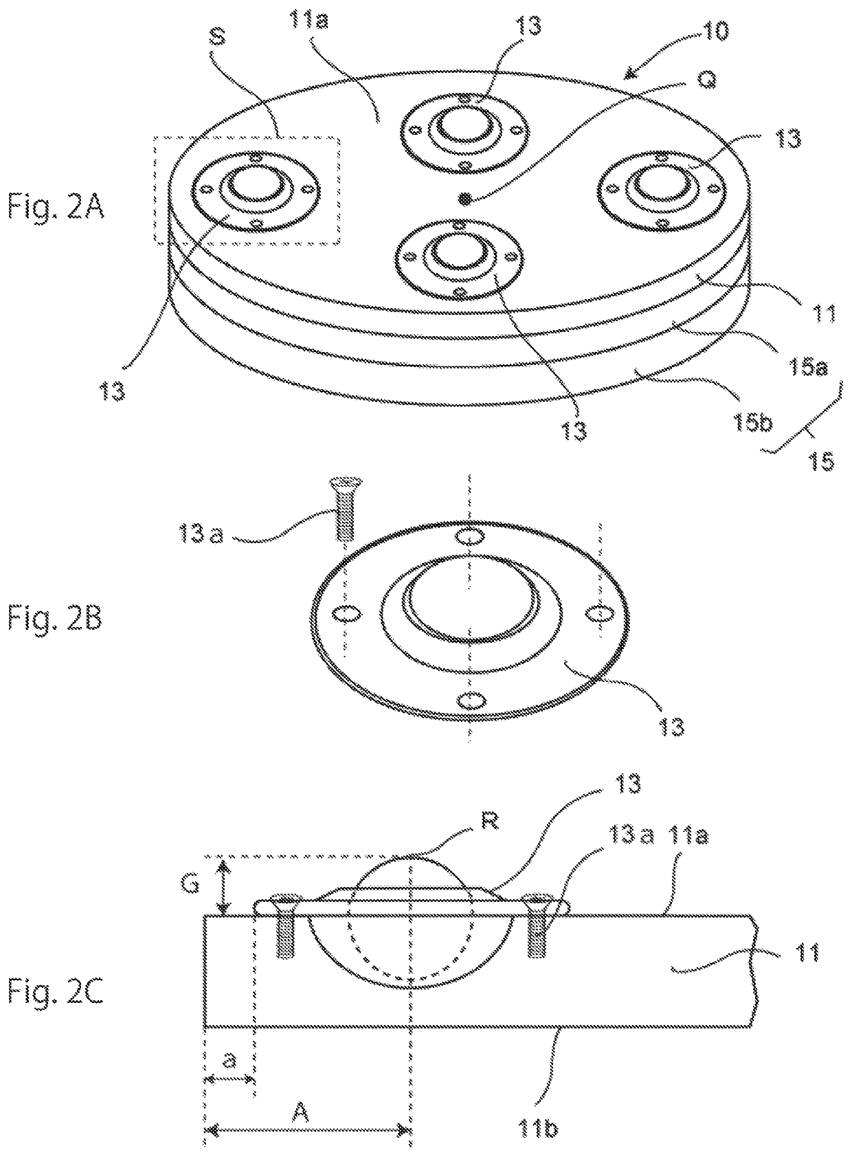
[0054]FIG. 1 is a perspective view for describing a stretching slider 10 of a first embodiment (hereinafter, sometimes referred to as a stretching slider (No. 1)). Specifically, FIG. 2A is a perspective view of the stretching slider 10 that is viewed from a second surface. FIG. 2B is an enlarged perspective view of a ball roller 13. FIG. 2C is a side view describing a preferable disposition relationship of the ball roller 13 with respect to a plate-shaped member 11.

[0055]1. Plate-Shaped Member

[0056]The stretching slider 10 of the first embodiment includes the plate-shaped member 11 and a plurality of the ball rollers 13. The plate-shaped member 11 has a first surface 11b as a front surface and a second surface 11a as a back surface.

[0057](1) Constituent Material

[0058]Although not particularly limited, the constituent material of the plate-shaped member 11 preferably includes at least one selected from wood, metal, resin, and ceramic in consideration of the life, cost, and the like r...

second embodiment

[0117]A stretching slider 20 of a second embodiment (hereinafter, sometimes referred to as a stretching slider (No. 2)) is provided with five ball rollers 13 on the second surface 11a of the plate-shaped member 11.

[0118]It is preferable that the five ball rollers 13 are disposed at positions corresponding to the five vertices of a regular pentagon.

[0119]As illustrated in FIG. 4A, the sitting of the plate-shaped member 11 is better in a case where five ball rollers 13 are used than in a case where four ball rollers 13 are used. As a result, the stability of the stretching slider 20 is improved.

third embodiment

[0120]As illustrated in FIG. 4B, a stretching slider 30 of a third embodiment (hereinafter, sometimes referred to as a stretching slider (No. 3)) is an example in which ball rollers 13x provided on the second surface 11a of the plate-shaped member 11 are smaller in size than the ball rollers of the first embodiment and larger in number than in the first and second embodiments. Ten ball rollers are provided in the illustrated example.

[0121]In the case of the stretching slider 30 of this third embodiment, the distance between the center point of each of the plurality of ball rollers 13x and the edge portion of the plate-shaped member 11 and the height of protrusion of the ball roller 13x from the second surface 11a can be further reduced as compared with the first embodiment.

[0122]Further, the ball roller 13x can be provided at a high density, and thus the stability of the stretching slider 30 is improved and the stretching slider 30 is unlikely to tilt even when an external force is ...


PUM


Abstract

Provided is a stretching slider excellent in compactness and lightweightness and exhibiting high stability and slipperiness. A stretching slider includes a plate-shaped member having a first surface as a front surface and a second surface as a back surface and a plurality of ball rollers provided on the second surface for moving the plate-shaped member in all directions along a horizontal direction.

Description

BACKGROUND OF THE INVENTION1. Field of the Invention[0001]The present invention relates to a lightweight and compact stretching slider for health promotion (sometimes briefly called as a slider), muscle strength enhancement, and the like.2. Description of the Related Art[0002]US 2005 / 0,209,072 (FIGS. 7A and 7B, FIG. 1, paragraphs 38-40, etc.) discloses an example of stretching sliders of the related art. FIGS. 7A and 7B are explanatory diagrams of this stretching slider 100. Specifically, FIG. 7A is a diagram illustrating an example of use of the stretching slider 100 and FIG. 7B is a side view illustrating an overview of the stretching slider 100.[0003]The stretching slider 100 of the related art includes a spherical body 101 large enough to be gripped by a palm and a strap 102 provided on the top surface portion of the spherical body 101.[0004]Provided in the spherical body 101 are one large roller ball 101a, an upper cover 101b, a lower cover 101c, a bearing system 101d, and a fi...

Claims


Application Information

Patent Timeline
IPC IPC(8): A63B22/20A63B21/00A63B23/00A63B23/12
CPCA63B22/20A63B21/0004A63B21/4035A63B21/4043A63B23/1236A63B2023/003A63B2071/025A63B2071/0625A63B2208/12A63B2209/00
Inventor MORIDAIRA, SHIGEO
Owner JUTE INC
Why Eureka
Try Eureka