Flow cell for a dissolution test device

a test device and flow cell technology, applied in the field of flow cell for dissolution test apparatus, can solve the problems of leakage between the water circuit and the test medium circuit, impurities and loss of dissolved active ingredient or specimen,

Active Publication Date: 2021-03-09
ERWEKA APPBAU
View PDF3 Cites 0 Cited by
  • Summary
  • Abstract
  • Description
  • Claims
  • Application Information

AI Technical Summary

Benefits of technology

[0019]This enables secure guiding of the parts and at the same time allows for a user-friendly disassembly. Since no electrical or mechanical clamping device on the top of the cell head has to be attached during the screwing, the outlet opening for the test medium, which in the state of the art is always arranged on the side of the head, can be arranged on the top.
[0020]This also ensures improved flow guidance in the head area, because the 90° deflection of the flow is eliminated. A further result is a more uniform use of filter surfaces. According to the invention, the filter is arranged in the hollow, screwable filter head. The previously common variants can be omitted. The filter is housed uniformly as a filter pack in the filter head above the seal, allowing for easier insertion.
[0021]According to another advantageous feature of the present invention, the seal between the cell mount, with which the flow cell is mounted on the water bath, and the sample cell is accomplished via an end side flat gasket. Since the individual parts are accurately guided by the screwing and due to the fact that the flat gasket is configured wider than the torpid O-seals, a better seal is achieved, which is also less prone to handling errors of laboratory staff, since tilting can be practically ruled out.
[0022]According to another advantageous feature of the present invention, the sealing between the cell casing and the cell mount and between the cell casing and the filter head is accomplished with a respective end-face flat gasket. This reliably prevents leakage to the outside and within the filter head. Especially the latter area is critical for the measurements, due to the risk of mixing of water and test medium in this area.
[0024]According to another advantageous feature of the present invention, the dissolution test apparatus includes seven flow cells according to the invention. This makes it possible to perform all test variants required for the dissolution tests in a single-pass run with a single apparatus.

Problems solved by technology

However, in the state of the art sealing of the flow cells frequently involves problems that lead to leaks between the water circuit and the test medium circuit.
As a result, water may enter and undesirably dilute the test medium or test medium may leak into the water where it causes impurities and loss of dissolved active ingredient or specimen.
Such measurement errors are already caused by minor inaccuracies in the alignment of the assembled parts.
It is difficult to detect this error source during operation, unless a complete leakage of the cell occurs.
As a result, the measurements are not reproducible and in the case of test protocols in which several samples are measured in parallel, large fluctuations occur within a set of measurements.
In addition, leakage of test medium into the cell casing means a considerable loss of time for a series of measurements, since it is then not sufficient to merely re-load the sample cell for the next measurement, but the water in the water bath has to be exchanged and all flow cells and the water bath must be cleaned.

Method used


Image

  • Flow cell for a dissolution test device
  • Flow cell for a dissolution test device

Examples


Embodiment Construction

[0028]Throughout all the Figures, same or corresponding elements may generally be indicated by same reference numerals. These depicted embodiments are to be understood as illustrative of the invention and not as limiting in any way. It should also be understood that the figures are not necessarily to scale and that the embodiments are sometimes illustrated by graphic symbols, phantom lines, diagrammatic representations and fragmentary views. In certain instances, details which are not necessary for an understanding of the present invention or which render other details difficult to perceive may have been omitted.

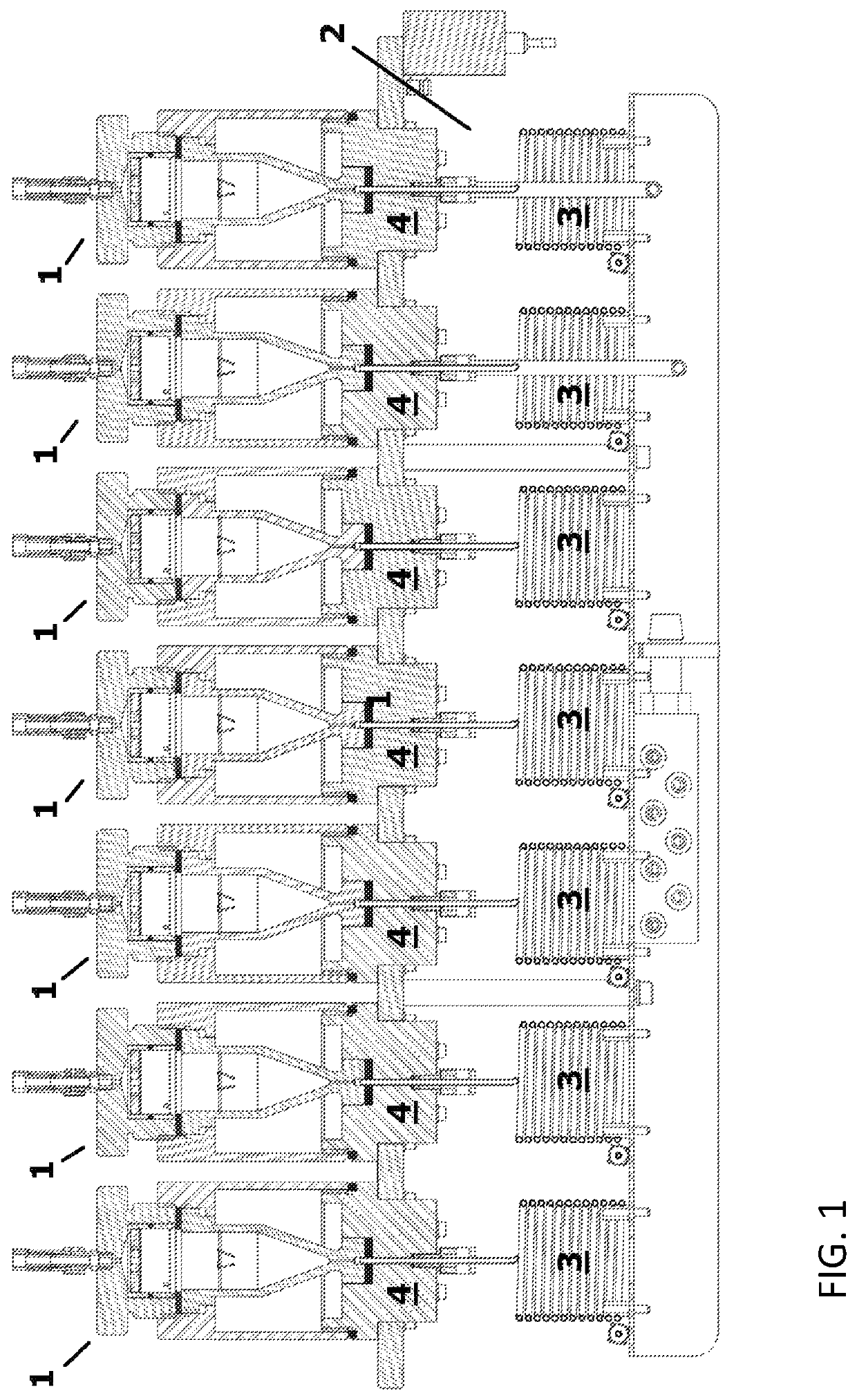
[0029]Turning now to the drawing, and in particular to FIG. 1, there is shown a sectional view of a preferred variant of the dissolution test device according to the invention with seven flow cells. By means of their cell mounts 4 the seven flow cells 1 are mounted on the water bath 2 of the test device into which the heating coils 3 of the flow cells 1 dip. The cell mounts ...


PUM

PropertyMeasurementUnit
temperatureaaaaaaaaaa
constant flow rateaaaaaaaaaa
temperature stabilityaaaaaaaaaa

Abstract

A flow cell for a dissolution test apparatus, Includes a cell mount, a filter head, a cylindrical cell casing connected with the cell mount and with the filter head via threads provided on respective ends of the cylindrical cell casing, and a sample cell received in the cell casing and co figured for receiving a sample.

Description

CROSS-REFERENCES TO RELATED APPLICATIONS[0001]This application claims the priority of German Patent Application, Serial No. 10 2017 102 761.0 filed Feb. 13, 2017, pursuant to 35 U.S.C. 119(a)-(d), the content of which is incorporated herein by reference in its entirety as if fully set forth herein.BACKGROUND OF THE INVENTION[0002]The present invention relates to a flow cell for a dissolution test apparatus and a corresponding dissolution test apparatus.[0003]The following discussion of related art is provided to assist the reader in understanding the advantages of the invention, and is not to be construed as an admission that this related art is prior art to this invention.[0004]Testing the properties of powdered and granular drugs, tablets, suppositories, implants and stents also includes testing their dissolution properties. For this purpose, the test specimens are placed in dissolution test equipment in a flow cell, where they are bathed with a test medium at a defined temperatur...

Claims


Application Information

Patent Timeline
Patent Type & Authority Patents(United States)
IPC IPC(8): B01L3/00G01N33/15G01N21/05G01N13/00G01N1/38B01D35/04G01N35/00
CPCB01L3/508B01D35/04G01N1/38G01N13/00G01N21/05G01N33/15B01D2201/342B01L2200/026B01L2200/06B01L2200/0689B01L2200/087B01L2200/14B01L2300/0681B01L2300/0832G01N2013/006G01N2035/00198
Inventor MÜLLER, WERNER G.BOZKURT, LEVENT
Owner ERWEKA APPBAU
Why Eureka
Try Eureka