Polishing holder for workpiece end surface

a technology for polishing holder and workpiece end surface, which is applied in the direction of grinding drive, grinding machine components, manufacturing tools, etc., can solve the problems of little unparallel phenomenon, inconvenient automation, and inability to accurately parallel the polishing surface and the other way around, so as to save production time and cost, improve the polishing quality, and facilitate manufacturing.

Active Publication Date: 2010-09-16
LING KOW JE
View PDF8 Cites 1 Cited by
  • Summary
  • Abstract
  • Description
  • Claims
  • Application Information

AI Technical Summary

Benefits of technology

[0018]For further improving a supporting structure between a main body and a framework of a optical fiber end surface polishing holder to allow the supporting structure to be manufactured more easily to save the production time and cost; besides, a position of the main body corresponding to a polishing surface can be changed in the process of polishing to allow each polishing point of the polishing surface rather to be uniformly used so as to elevate the polishing quality. Hence, the present invention is proposed.
[0019]The main object of the present invention is to provide a polishing holder for a workpiece end surface, allowing supporting structures of a main body and a framework to be manufactured more easily.
[0020]Another object of the present invention is to provide a polishing holder for a workpiece end surface, allowing an optical fiber end surface on a main body to be uniformly brought into contact with each area of a polishing surface; each polishing point of the polishing surface can be uniformly worn and torn to enable the polished degree of each optical fiber end surface to be more uniform so as to elevate the polishing yield factor of all the optical fiber end surfaces.
[0021]Still another object of the present invention is to provide a polishing holder for a workpiece end surface allowing each optical fiber to be arranged and retained more conveniently while being polished.

Problems solved by technology

But, there is still one problem; because the holder 41 is clipped to fix and the direction of the polishing surface 45 is also fixed in this design, in general, the holder 41 and the polishing surface 45 certainly not be able to be accurately parallel to each other.
But, this is not a natural contact such that a little unparallel phenomenon certainly exists.
Besides, the pressure between the end surface of the optical fiber 43 and the polishing surface is exerted upwards from below; such kind of manner is not only complex but also inconvenient to be automated.
Furthermore, if the polishing surface is linear as FIG. 2 shows and the many optical end surface holders are disposed and simultaneously slid on this linear polishing surface, it is then difficult to maintain the uniform pressure of the optical fiber end surface at different positions on each holder.
Besides, bottom ends of the four fixing rods 65 of the main body 60 must be kept at the same plane to cause the manufacturing to be very difficult.

Method used


Image

  • Polishing holder for workpiece end surface
  • Polishing holder for workpiece end surface
  • Polishing holder for workpiece end surface

Examples


Embodiment Construction

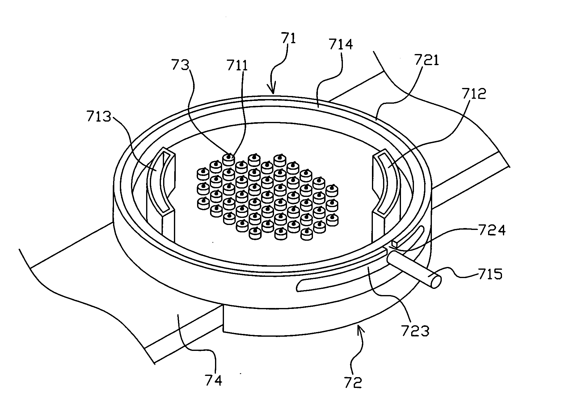
[0039]Please refer to FIGS. 7 and 8. A holder of a first preferred embodiment according to the present invention comprises a main body 71 and a framework 72. The main body 71 is coupled to a plurality of fixtures 711; each fixture 711 is coupled to at least one fiber end surface ferrule to couple to an optical fiber 73. Sides of the main body 71 close to a periphery thereof are provided with a plurality of accepting grooves 712, 713 to accept counterweights utilized to exert a downward pressure on the main body 71. But, if there is no counterweight added to exert the downward force on the main body 71, a rotational speed of a polishing surface may be controlled by a friction force between the polishing surface and optical fiber end surfaces, a rotational angle speed of the polishing surface must be far smaller than a revolutionary angle speed thereof. The accepting grooves 712, 713 respectively are a curved groove, cylindrical groove or long groove. A periphery of the main body 71 i...


PUM


Abstract

A polishing holder for a workpiece end surface comprises a main body and a framework, in which the main body is coupled to a plurality of fixtures used for coupling to polished-to-be workpieces, a periphery of the main body is provided with a ring first supporting portion; a framework, provided with a second supporting portion surrounding an outside of the first supporting portion. Whereby, the second supporting portion limits a deviation region of the first supporting portion to enable the main body to be kept parallel to a polishing surface during a polished end surface of the workpiece is brought into contact with the polishing surface and polished thereby so that the production time and cost of the first supporting portion can be reduced broadly.

Description

BACKGROUND OF THE INVENTION[0001]1. Field of the Invention[0002]The present invention relates to a polishing apparatus for a workpiece end surface, and more particularly to a holder for supporting a polished-to-be optical fiber end surface.[0003]2. Description of Related Art[0004]Optical fiber communication is an indispensable communication tool at the present and in the future. The main structure of an optical fiber connector used for the optical fiber communication, as FIG. 1 shows, is constituted by allowing a fiber optical 11 to be passed through a ferrule 12 and then adhered to the ferrule 12 with an adhesive. The ferrule 12 can be made from plastic, glass or ceramics. A projecting spherical surface 121 of the end surface of the ferrule 12 is pressed on an elastic polishing surface and formed by means of coarse grinding, fine grind and polishing. The projecting spherical surface 121 must be a flawless curved surface. Here, an optical axis of the projecting spherical surface 121...

Claims


Application Information

Patent Timeline
Patent Type & Authority Applications(United States)
IPC IPC(8): B24B41/06B24B19/00
CPCB24B41/067B24B19/226A61P31/12A61P31/18
Inventor LING, KOW-JE
Owner LING KOW JE
Why Eureka
Try Eureka