System and method for separating air gases at low pressure

Pending Publication Date: 2022-03-03
LAIR LIQUIDE SA POUR LETUDE & LEXPLOITATION DES PROCEDES GEORGES CLAUDE
View PDF0 Cites 0 Cited by
  • Summary
  • Abstract
  • Description
  • Claims
  • Application Information

AI Technical Summary

Benefits of technology

The invention relates to a method for purifying air using adsorbers. The choice of pressure P1 is important and should allow for low-pressure technology in the adsorber casings with flat surfaces rather than cylindrical casings. A pressure of 1.5 bar abs (4.1-4.2 MPa) for example, allows for the use of parallelepipedal adsorbers, optionally with several reinforcements on the flat surfaces. It also results in an improved adsorption capacity of about 40% compared to an atmospheric pressure solution. The amount of water that can be introduced is smaller and the corresponding rise in temperature is smaller, as well. Additionally, the invention also includes a system to prevent local pollution of the purified air, which may be caused by bypass or regeneration faults.

Problems solved by technology

As already indicated, it is practically impossible to reach this level of precision with a flat adsorbent bed having a large free surface.

Method used


Image

  • System and method for separating air gases at low pressure
  • System and method for separating air gases at low pressure
  • System and method for separating air gases at low pressure

Examples


Embodiment Construction

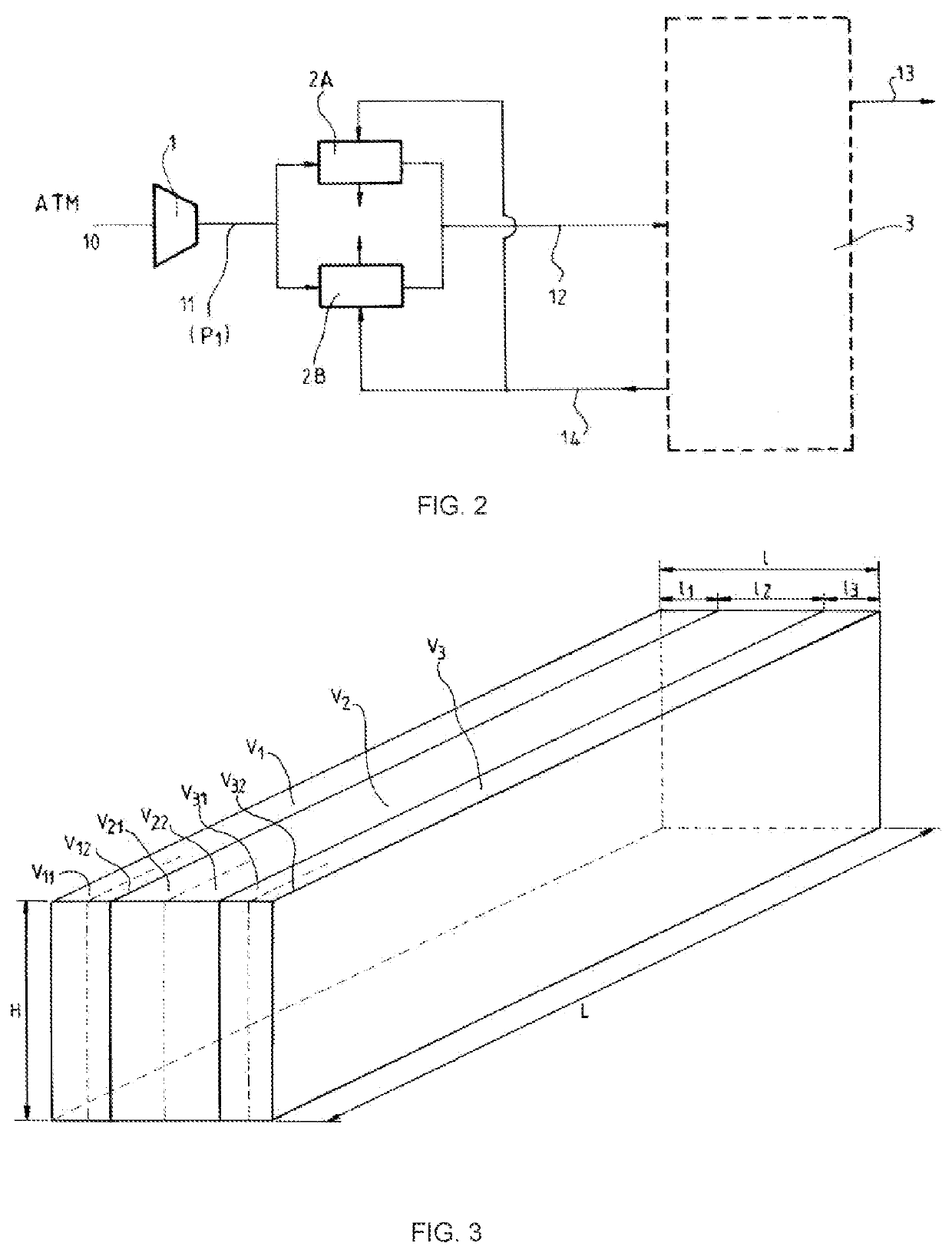
[0066]The adsorber A of the plant according to invention will be described in greater detail by means of FIG. 3. Specifically, that figure shows the various volumes V1, V2 and V3 and any sub-volumes there might be. A “parallelepipedal shape” is given to mean that in practice, the adsorber casing has six flat faces and has the appearance of a parallelepiped, but that it may have reinforcements, locally at least one internal or external layer of insulation, and obviously pipes or tanks for introducing and withdrawing air and regeneration gas. With the adsorber laid down flat, its longest length is denoted as L, its width as l and its height as H. In the context of the invention, it is not important whether these are external or internal dimensions.

[0067]FIG. 3 clearly shows that the volumes and sub-volumes are all of parallelepipedal shape and all have the same length L and the same height H. The parallelepipeds that they form differ from one another only in terms of their width.

[0068...


PUM


Abstract

An air gas separation plant comprising, in the direction of circulation of the air stream: a compression means that makes it possible to compress the air stream to a pressure P1 of between 1.15 bar abs and 2 bar abs, an adsorption unit of TSA type, and a cryogenic distillation unit, with the adsorption unit comprising at least two adsorbers A and B each having a parallelepipedal casing arranged horizontally and comprising: an air stream inlet and an air stream outlet, a fixed bed adsorbent mass, likewise of parallelepipedal shape, the faces of which are parallel to the faces of the casing; and a set of volumes allowing the air stream to pass through the adsorbent mass horizontally, over the entire cross-section and throughout the entire thickness thereof.

Description

CROSS REFERENCE TO RELATED APPLICATIONS[0001]This application is a § 371 of International PCT Application PCT / FR2020 / 050254, filed Feb. 12, 2020, which claims the benefit of FR1901731, filed Feb. 21, 2019, both of which are herein incorporated by reference in their entireties.FIELD OF THE INVENTION[0002]The present invention relates to a plant for aerial gas separation and to the process for aerial gas separation using said plant. More specifically, it relates to purifying the atmospheric air before separation of said air by cryogenic distillation.BACKGROUND OF THE INVENTION[0003]It is known that atmospheric air contains compounds that must be removed before it is introduced into the heat exchangers of the cold box of an air separation unit, particularly water vapor (H2O), carbon dioxide (CO2), nitrogen oxides and hydrocarbons.[0004]Indeed, in the absence of such treatment of the air in order to remove its H2O and CO2 impurities, these impurities solidify when the air is cooled to c...

Claims


Application Information

Patent Timeline
IPC IPC(8): F25J3/04B01D53/04
CPCF25J3/04181F25J3/04775B01D53/0462B01D53/0446F25J2205/60B01D2259/402F25J2210/06B01D2257/504B01D2257/404B01D2257/702B01D2257/80F25J2290/12F25J3/04169F25J3/04866B01D53/0407B01D2256/10B01D2256/12Y02C20/40
Inventor DAVIDIAN, BENOIT
Owner LAIR LIQUIDE SA POUR LETUDE & LEXPLOITATION DES PROCEDES GEORGES CLAUDE
Why Eureka
Try Eureka