Device for producing a tubular container

a technology for tubular containers and containers, applied in the direction of dykes, excavations, embankments, etc., can solve the problem of providing a very complex construction, and achieve the effect of ensuring the maneuverability of the device and sufficient dimensional stability

Active Publication Date: 2021-03-09
TOPOCARE GMBH
View PDF16 Cites 0 Cited by
  • Summary
  • Abstract
  • Description
  • Claims
  • Application Information

AI Technical Summary

Benefits of technology

[0002]Tubes manufactured from geotextile material which are preferably filled with sand, but also with gravel, crushed stone, earth materials, or similar building materials, are of particular use for the erection of embankments, e.g. protective structures such as levees, noise embankments, etc. As such, the geotextile material has sufficient strength to retain granular materials within a matrix, wherein the geotextile may be permeable or impermeable to water. Thus, tubes manufactured in this manner may be advantageously employed in the construction of dams, where, in addition to the formation of permanent structures, they can be used to repair dams and erect temporary structures. A dam formed with such tubes has a high stability, the tubes in particular withstanding flooding of the dam.
[0005]Therefore, an aspect of the invention addresses the problem of providing a device for producing a tubular container which is immediately and quickly operational, wherein the device is to be more light-weight and less costly when it comes to construction and transport volume.
[0006]The advantages achieved with an aspect of the invention are now that the device according to the invention is lightweight and easy to handle in that it can be readily and quickly deployed on site wherever a filled geotextile tube is to be formed, for example. The device now offers the possibility that a tubular container can be formed quickly and readily by filling the displaceable frame of the device in conjunction with the stored geotextile material. As such, the device is pulled by its own drive or by a traction unit, wherein a simple filling of the material into the filling trough may also be accomplished using a shovel loader. When displacing the device, the filled tube is formed by the advancement, the tube being laid by the device such that a geotextile web from below, on the one hand, and a geotextile web from above form the enclosed tube for the material. As such, the closing of the geotextile web by the edge zones is preferably achieved by overlapping them around the first geotextile web, wherein the bond underneath the tube is created by the self-weight of the overlying material.
[0012]According to a particularly advantageous further development, the rear loading zone consists of or comprises an unwinding axis for the second geotextile web, which is horizontally disposed above the outlet hopper, and a guiding device for the edges of the second geotextile web, which is disposed at the outer wall of the outlet hopper. The unwinding process is accomplished such that the edges drag along the outer walls of the outlet upper during movement of the frame in such a manner that the guiding device comprises two converging tracks bent opposite each other along the outer wall of the outlet hopper towards the discharge, enabling the layers of both edges of the second geotextile to overlay each other underneath the hopper outlet towards the discharge.
[0014]According to a particularly advantageous further development, as already detailed above, the first geotextile web is provided with a tensioning element which is tensioned between the edges of the geotextile web during filling. When displacing the frame, the geotextile web is dragged into the inner filling trough zone, the web unfolding either at the bottom or such that the geotextile abuts on the walls of the trough and is spread, for example, if the geotextile web is provisioned in a folded state. In this case, the tensioning element in the form of a net may be incorporated between the edges of the web which ensures sufficient dimensional stability of the round shape of the tube in the diametral axis of the laid filled tube.
[0015]In a further development of an aspect of the invention, the frame is provided with its own drive. As an example, this drive may comprise a crawler track which may be disposed with a universal joint or ball joint underneath the frame. This configuration ensures the maneuverability of the device so that the tube can be laid in any direction. Another development of the displaceable frame can be designed such that the frame is configured as a trailer which may cooperate with a traction unit. In this case, the frame has an axle disposed with balloon wheels underneath the outlet hopper. The structure of the device enables the device to be moved over tubes already laid such that tubes may be accordingly laid one above the other in this case.

Problems solved by technology

Such a prior-art device has disadvantages in that it provides a very complex construction and is only suitable for machine laying of filled geotextile tubes.
However, it is often demanded that tubes be formed particularly quickly and without major provision of infrastructure to thereby obtain a barrier or embankment which is to be built directly on site.

Method used


Image

  • Device for producing a tubular container
  • Device for producing a tubular container
  • Device for producing a tubular container

Examples


Embodiment Construction

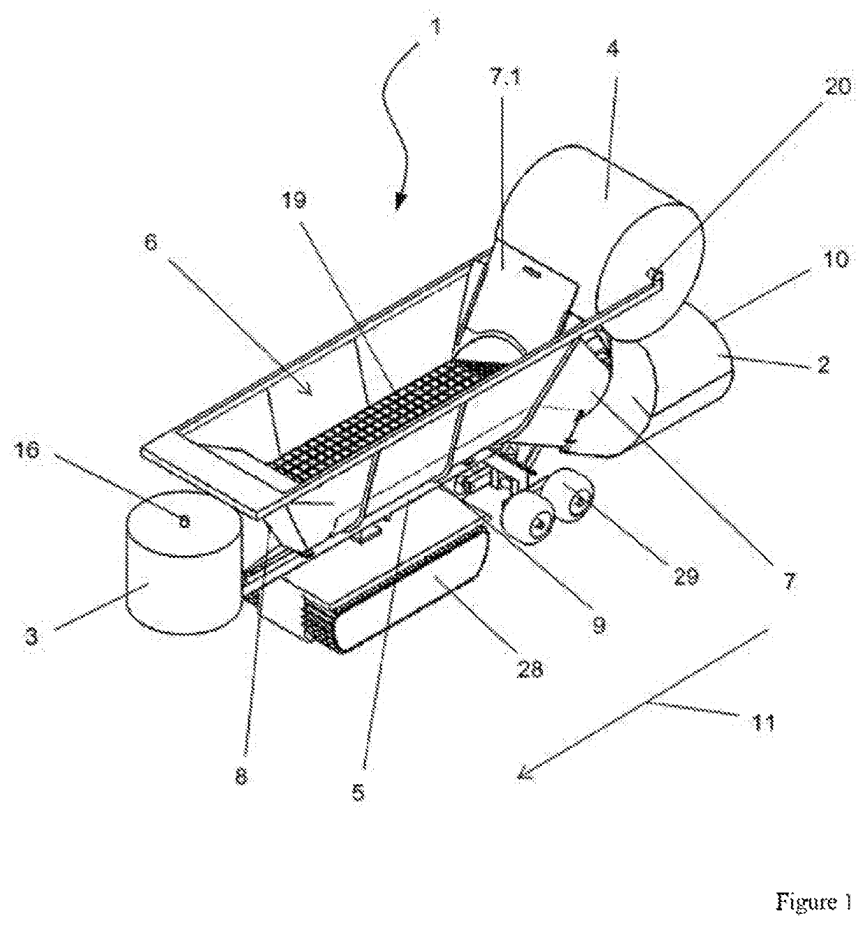
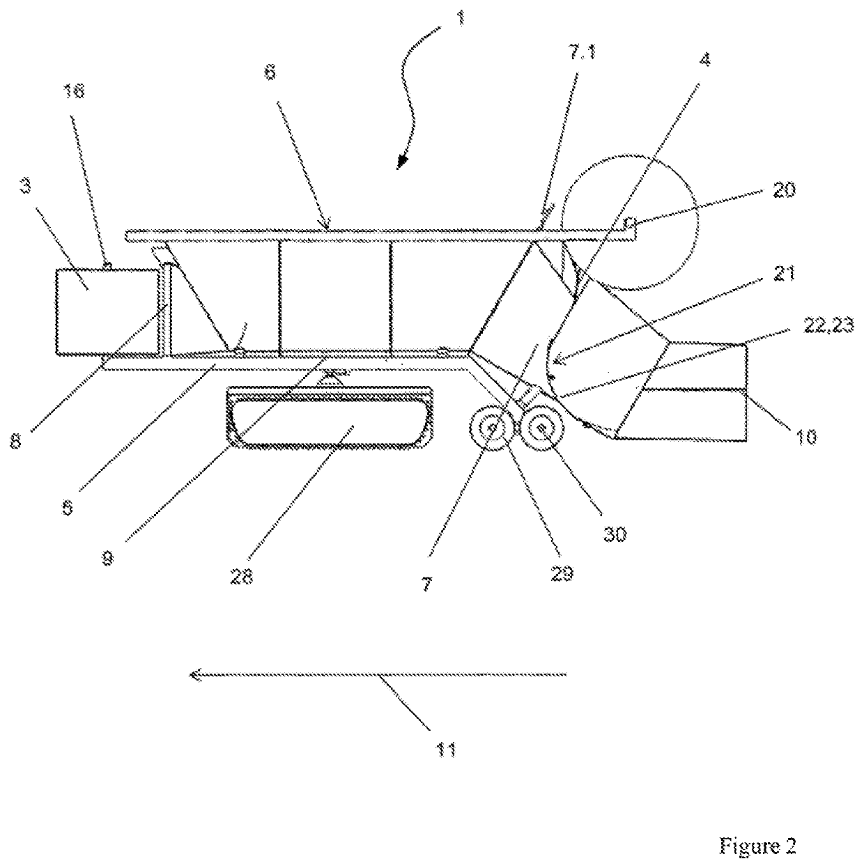
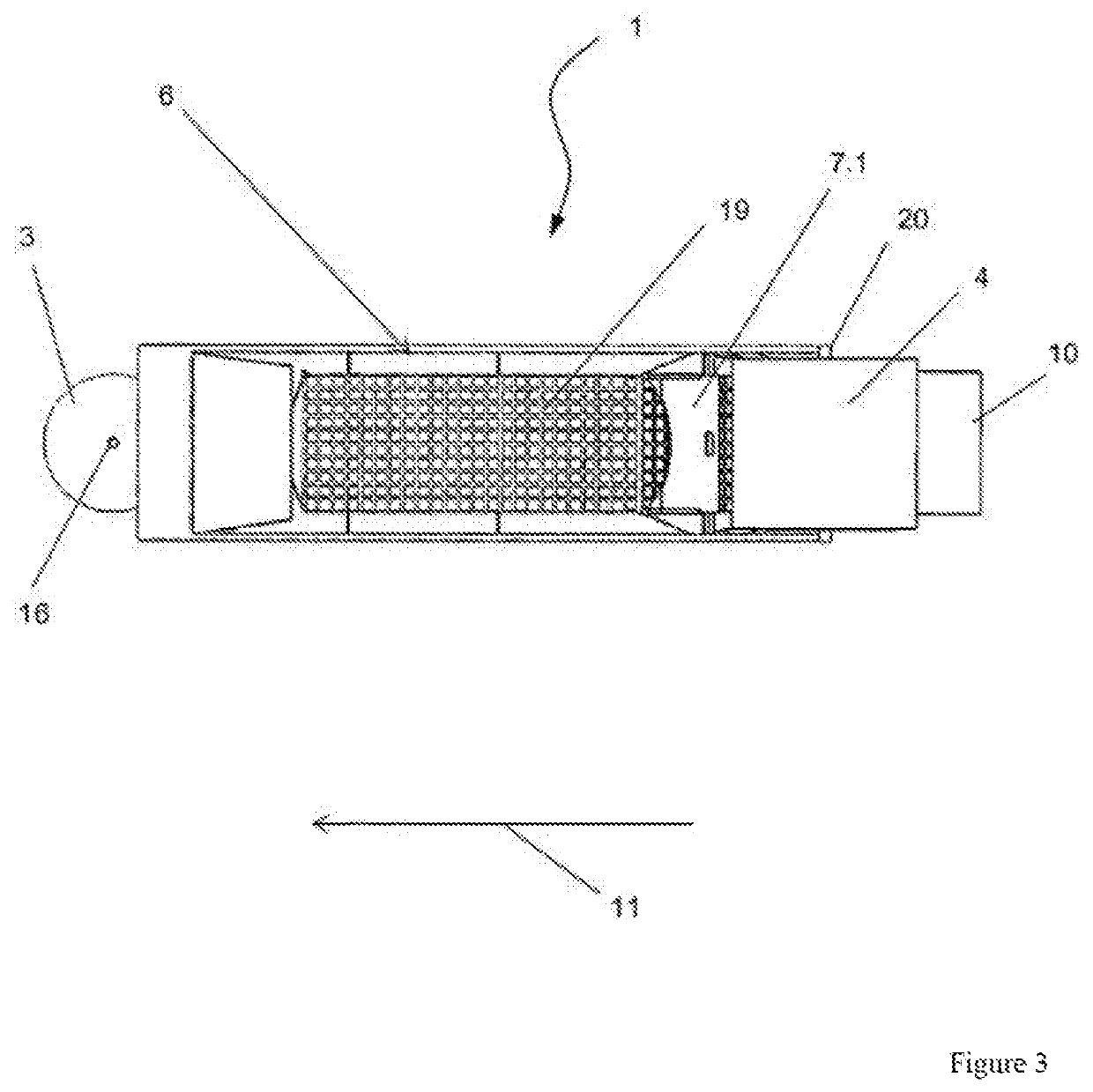
[0024]FIGS. 1, 2, and 3 show an embodiment of a device 1 for producing a tubular container 2, as indicated in FIG. 2. In this case, container 2 consists of or comprises a granular, pulverulent, pourable or flowable material which, in the example shown, is surrounded by webs 3 and 4 manufactured from geotextile material.

[0025]As can best be recognized when looking at FIGS. 1 and 2 together, device 1 consists of or comprises a displaceable frame 5 having a filling trough 6 for the material. At its rear end, filling trough 6 has an outlet hopper 7 for the material, wherein, at the front end, a first loading zone 8 is provided for a first unwindable geotextile web 3, which is guided on a trough bottom 9 as frame 5 is advanced.

[0026]At the rear end of filling trough 6, a second loading zone for a second unwindable geotextile web 4 is provided, surrounding the material filled onto the first unwound geotextile web 3 in an enveloping manner upon advancement to form a tube 10, as shown in FI...


PUM

PropertyMeasurementUnit
weightaaaaaaaaaa
movementaaaaaaaaaa
tensionaaaaaaaaaa

Abstract

A device is provided for producing a tubular container which is able to be filled with granular, pulverulent, pourable and flowable materials, wherein the container can include webs manufactured from geotextile material. The device includes a displaceable frame with at least one unwindable geotextile web, wherein the frame includes a filling trough with an outlet hopper for the material, and wherein the filling trough has a conveying device for the filled material, the conveying device acting counter to the direction of movement of the frame, which, at the rear end of the filling trough, surrounds the material in an enveloping manner, in the region of the outlet hopper, by the unwindable geotextile web, as the frame is advanced, so as to form a tube.

Description

BACKGROUND AND SUMMARY[0001]The invention relates to a device for producing a tubular container which is able to be filled with granular, pulverulent, pourable materials, wherein the container preferably consists of or comprises a web manufactured from geotextile material.[0002]Tubes manufactured from geotextile material which are preferably filled with sand, but also with gravel, crushed stone, earth materials, or similar building materials, are of particular use for the erection of embankments, e.g. protective structures such as levees, noise embankments, etc. As such, the geotextile material has sufficient strength to retain granular materials within a matrix, wherein the geotextile may be permeable or impermeable to water. Thus, tubes manufactured in this manner may be advantageously employed in the construction of dams, where, in addition to the formation of permanent structures, they can be used to repair dams and erect temporary structures. A dam formed with such tubes has a ...

Claims


Application Information

Patent Timeline
Patent Type & Authority Patents(United States)
IPC IPC(8): B65B9/00B65B1/02B65B1/04B65B9/02B65B9/06B65B9/13E02D17/18B65B43/54E02B3/12B65B41/12E02B3/10E02D17/20
CPCB65B1/02B65B1/04B65B9/023B65B9/06B65B9/13B65B41/12B65B43/54E02B3/108E02B3/127E02B3/128E02D17/18E02D17/202E02D2200/1685E02D2250/00E02D2300/0085
Inventor DRAIER, ROLAND
Owner TOPOCARE GMBH
Why Eureka
Try Eureka