Piezoelectric MEMS-based active cooling for heat dissipation in compute devices

a technology of active cooling and compute devices, applied in the direction of mechanical vibration separation, positive displacement liquid engines, modification by conduction heat transfer, etc., can solve the problems of affecting processor speed, generating a significant amount of heat, and high clock speed of smart phones, tablets and notebooks

Active Publication Date: 2021-03-09
FRORE SYST INC
View PDF58 Cites 19 Cited by
  • Summary
  • Abstract
  • Description
  • Claims
  • Application Information

AI Technical Summary

Benefits of technology

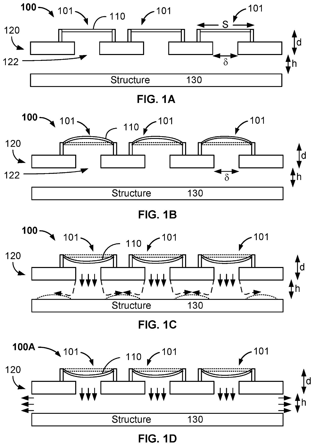
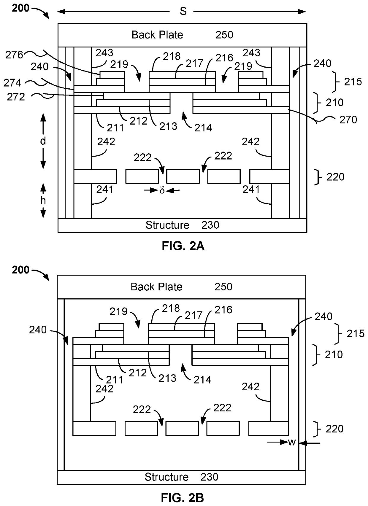
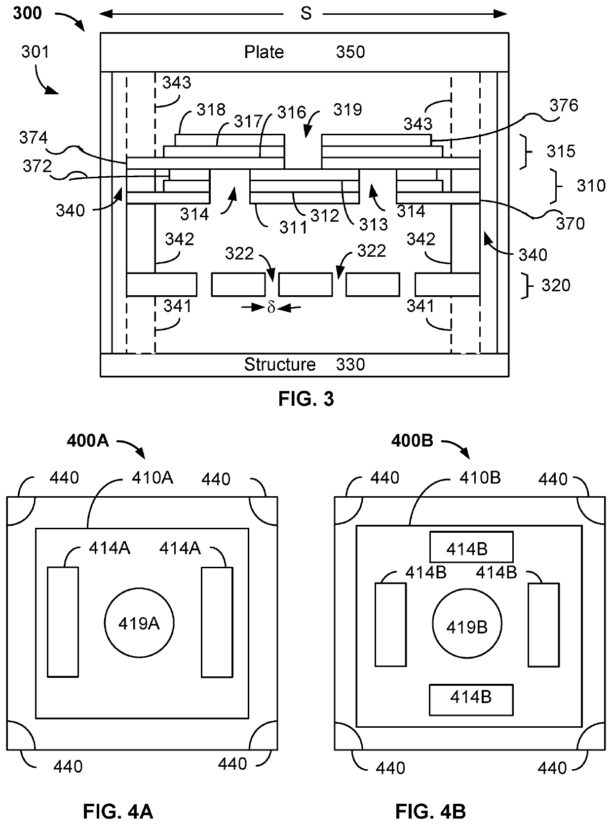
The patent text describes a cooling system for electronic devices that uses a piezoelectric actuator to transfer heat away from the device. The cooling system is designed to address the issue of excessive heat generated by powerful semiconductor devices such as processors. The technical effect of the invention is to provide an effective cooling solution that can improve the performance and longevity of such devices. Various embodiments of the cooling system are described in the patent text, including diagrams and descriptions of the piezoelectric actuator and orifice plate valve. The cooling system can be incorporated into mobile devices such as smartphones, tablets, and notebooks, improving their performance and reliability.

Problems solved by technology

For example, processors for mobile devices such as smartphones, tablets and notebooks can operate at high clock speeds, but produce a significant amount of heat.
Although throttling can reduce heat generation, it also adversely affects processor speed.
As a result, performance of devices using the processors suffers.
As technology moves to 5G and beyond, this issue is expected to be exacerbated.
However, such fans are typically too large for mobile devices such as smartphones, may have limited efficacy because of the boundary layer of air existing at the surface of the components, provide a limited airspeed for air flow across the surface of the devices and may generate an excessive amount of noise.
Although a heat spreader somewhat mitigates the temperature increase at hot spots, the amount of heat produced in current and future devices may not be adequately addressed.
Similarly, a heat pipe or vapor chamber may provide an insufficient amount of heat transfer to address excessive heat generated.

Method used


Image

  • Piezoelectric MEMS-based active cooling for heat dissipation in compute devices
  • Piezoelectric MEMS-based active cooling for heat dissipation in compute devices
  • Piezoelectric MEMS-based active cooling for heat dissipation in compute devices

Examples


Embodiment Construction

[0028]The invention can be implemented in numerous ways, including as a process; an apparatus; a system; a composition of matter; a computer program product embodied on a computer readable storage medium; and / or a processor, such as a processor configured to execute instructions stored on and / or provided by a memory coupled to the processor. In this specification, these implementations, or any other form that the invention may take, may be referred to as techniques. In general, the order of the steps of disclosed processes may be altered within the scope of the invention. Unless stated otherwise, a component such as a processor or a memory described as being configured to perform a task may be implemented as a general component that is temporarily configured to perform the task at a given time or a specific component that is manufactured to perform the task. As used herein, the term ‘processor’ refers to one or more devices, circuits, and / or processing cores configured to process da...


PUM


Abstract

An active cooling system and method for using the active cooling system are described. The active cooling system includes a cooling element having a first side and a second side. The first side of the cooling element is distal to a heat-generating structure and in communication with a fluid. The second side of the cooling element is proximal to the heat-generating structure. The cooling element is configured to direct the fluid using a vibrational motion from the first side of the cooling element to the second side such that the fluid moves in a direction that is incident on a surface of the heat-generating structure at a substantially perpendicular angle and then is deflected to move along the surface of the heat-generating structure to extract heat from the heat-generating structure.

Description

CROSS REFERENCE TO OTHER APPLICATIONS[0001]This application claims priority to U.S. Provisional Patent Application No. 62 / 717,474 entitled PIEZO ELECTRIC MEMS-BASED ACTIVE COOLING FOR HEAT DISSIPATION IN COMPUTE DEVICES filed Aug. 10, 2018 which is incorporated herein by reference for all purposes.BACKGROUND OF THE INVENTION[0002]As semiconductor devices become increasingly powerful, the heat generated during operations also grows. For example, processors for mobile devices such as smartphones, tablets and notebooks can operate at high clock speeds, but produce a significant amount of heat. Because of the quantity of heat produced, processors may run at full speed only for a relatively short period of time. After this time expires, throttling (e.g. slowing of the processor's clock speed) occurs. Although throttling can reduce heat generation, it also adversely affects processor speed. As a result, performance of devices using the processors suffers. As technology moves to 5G and bey...

Claims


Application Information

Patent Timeline
Patent Type & Authority Patents(United States)
IPC IPC(8): H05K7/20H01L23/473F04B53/10F04B43/04F04B45/047B06B1/06H01L23/427H01L23/433H01L41/09F25B21/02F04D33/00H04M1/02H01L41/02H01L41/00F04B43/09H01L23/46H01L23/42F04B17/00F04B45/04H01L41/08
CPCH01L23/473B06B1/06F04B17/003F04B43/046F04B43/095F04B45/043F04B45/047F04B53/1077F04D33/00F25B21/02H01L23/42H01L23/427H01L23/433H01L23/46H01L41/00H01L41/02H01L41/08H01L41/09H01L41/0926H01L41/0973H04M1/0202H05K7/20H05K7/20009H05K7/2039H05K7/20272H05K7/20281F25B2321/023F25B2321/025F25B2321/0212F25B2321/0252H01L23/467H05K7/20172F04B53/08F04B43/04F04B53/10B06B1/0622F25B21/00Y02B30/00Y02D10/00H01L23/4735H01L23/4336H10N30/00H10N30/20H10N30/80H10N30/204H10N30/2047H10N35/80F04B39/06F04B43/08
Inventor GANTI, SURYAPRAKASHMADHAVAPEDDY, SESHAGIRI RAO
Owner FRORE SYST INC
Why Eureka
Try Eureka