
Shredding assembly for a grinder pump and centrifugal grinder pump

a technology of grinding assembly and grinder pump, which is applied in the direction of specific fluid pump, non-positive displacement pump, non-positive displacement pump, etc., can solve the problems of complex and/or expensive maintenance work, and reducing the efficiency of the pump, so as to achieve fine shredding action of solid materials and clean cut

Active Publication Date: 2021-03-16
SULZER MANAGEMENT AG
View PDF20 Cites 0 Cited by
  • Summary
  • Abstract
  • Description
  • Claims
  • Application Information

AI Technical Summary

Benefits of technology

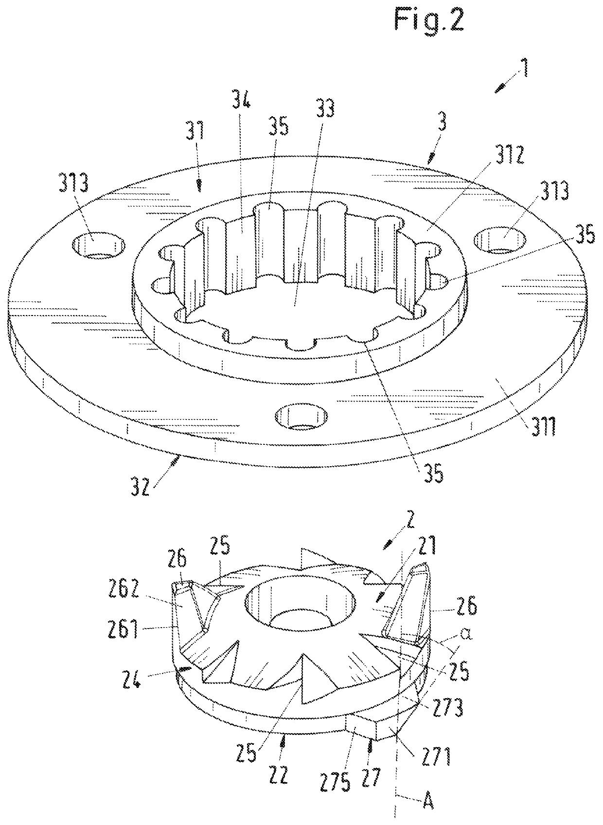
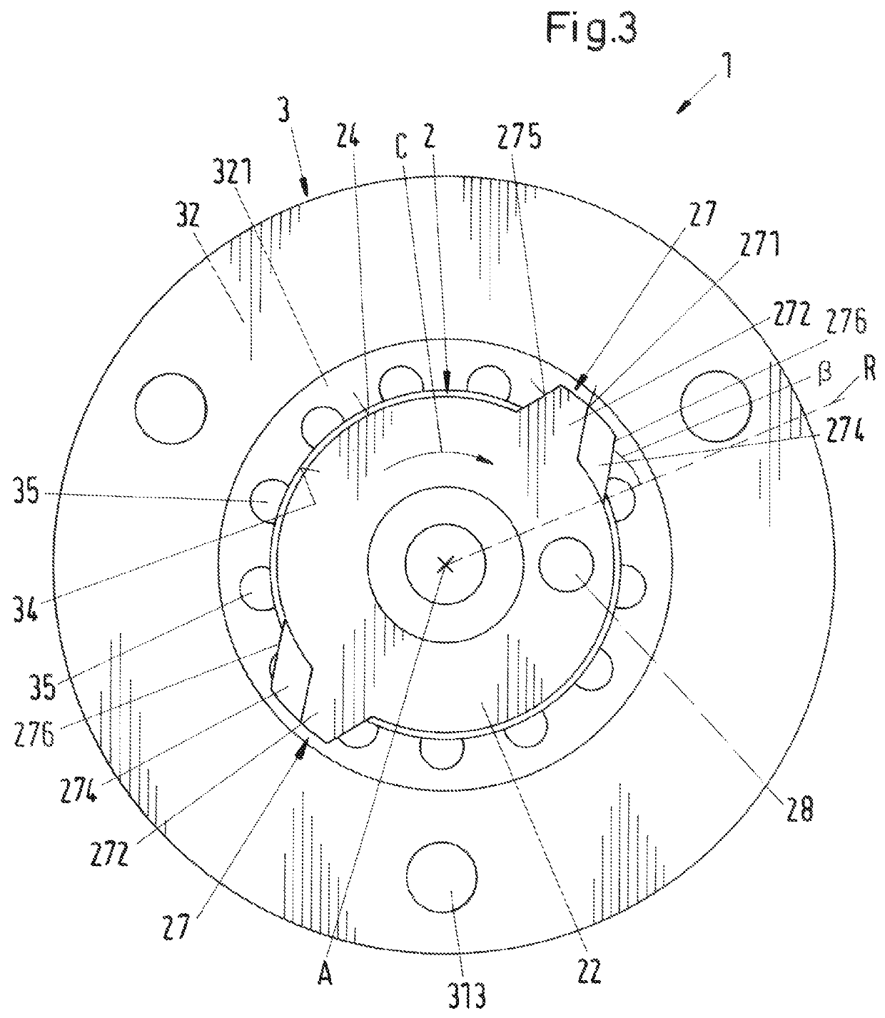
[0014]Preferably the first cutting members are configured to fit into the central opening of the shredding ring. Thus, the maximum extension of the first cutting members, or the front face of the cutting device, respectively, is smaller than the inner diameter of the central opening of the shredding ring, so that the first cutting members may freely rotate within the central opening.
[0032]By providing the centrifugal grinder pump with two impellers arranged in series, i.e. one after the other with respect to the axial direction, the head-flow range, in which the pump may be operated, is considerably extended as compared to pumps with only one impeller. In particular, the head that can be generated with the multistage centrifugal grinder pump is remarkably increased, so that the multistage grinder pump is particularly suited for high head applications requiring a head of, for example, up to 200 feet (61 meters) or even more. In addition, since the centrifugal grinder pump is preferably designed with an internal diffusor for guiding the fluid conveyed by the first stage impeller from the first impeller chamber to the second stage impeller, the grinder pump is very compact, because there is no need for an interstage conduit arranged at the outside of the housing and wrapping around the housing.

Problems solved by technology

When conveying sewage or waste water and in particular of domestic waste water, problems result because such liquids contain constituents such as fibrous materials, rags, cloths, textiles, plastic bags or other solids, which can very easily become stuck in the region of the pump and can then result in a reduction in the efficiency, in particular the hydraulic efficiency, of the pump up to the complete blocking of the impeller of the pump.
This can cause servicing or also complex and / or expensive maintenance work.
However, if gravity is not sufficient to move the sewage to the desired location or if gravity based systems are not economical, grinder pumps are used to lift the sewage or to convey the sewage over longer distances.
Such a high head in combination with a reasonable flow rate is at least very difficult if not impossible to realize with a centrifugal grinder pump having only one impeller.
However, the cutting or shredding action of these known designs is not always sufficient to ensure a proper operation of the grinder pump without the risk of the pump blocking or without a considerable reduction in the hydraulic efficiency of the pump.
In addition to the risk of blocking of one of the impellers there is also the likelihood that the transition from the first stage (first impeller) to the second stage (second impeller) is clogged by solid constituents in the liquid that are not sufficiently disintegrated by the shredding assembly.
Thus, in case the solid material in the liquid is not sufficiently comminuted there is considerable risk that the diffusor is clogged.

Method used


Image

  • Shredding assembly for a grinder pump and centrifugal grinder pump
  • Shredding assembly for a grinder pump and centrifugal grinder pump
  • Shredding assembly for a grinder pump and centrifugal grinder pump

Examples


Embodiment Construction

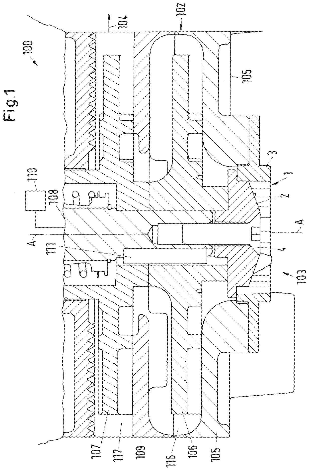
[0046]FIG. 1 shows a cross-sectional view of an embodiment of a centrifugal grinder pump according to the invention comprising an embodiment of a shredding device. The centrifugal grinder pump is designated in its entity with reference numeral 100, and the shredding device is designated in its entity with reference numeral 1.

[0047]In the following description reference is made by way of example to an embodiment of the centrifugal grinder pump 100, which is a multistage centrifugal pump, in particular a two stage pump. It goes without saying that the centrifugal grinder pump may also be a single stage grinder pump or as a multistage grinder pump having more than two stages, for example three stages or even more. Furthermore, reference is made by way of example to the important application that the centrifugal grinder pump is used for conveying sewage or wastewater in private, municipal or industrial areas. The sewage typically comprises solid constituents such as fibrous materials, r...


PUM


Abstract

A shredding assembly for a grinder pump includes a stationary shredding ring mounted to an inlet of the pump, and a cutting device rotatable about an axial direction and fixed to a shaft of the pump. The shredding ring includes a top face, a bottom face, and a central opening extending from the top face to the bottom face and delimited in a radial direction by an inner periphery. Slots extending in the axial direction are formed in the inner periphery. The cutting device is positioned in the central opening of the shredding ring, and includes a front face and a back face. The front face includes a plurality of first cutting members extending in the axial direction and facing the slots. The back face includes a second cutting member projecting beyond the central opening with respect to the radial direction.

Description

CROSS-REFERENCE TO RELATED APPLICATION[0001]This application claims priority to European Application No. 17205075.9, filed Dec. 4, 2017, the contents of which are hereby incorporated herein by reference.FIELD OF THE INVENTION[0002]The invention relates to a shredding assembly for a grinder pump and a centrifugal grinder pump.BACKGROUND OF THE INVENTION[0003]When conveying sewage or waste water and in particular of domestic waste water, problems result because such liquids contain constituents such as fibrous materials, rags, cloths, textiles, plastic bags or other solids, which can very easily become stuck in the region of the pump and can then result in a reduction in the efficiency, in particular the hydraulic efficiency, of the pump up to the complete blocking of the impeller of the pump. This can cause servicing or also complex and / or expensive maintenance work. Therefore, special measures have to be taken with such pumps in order to effectively prevent clogging.[0004]A known so...

Claims


Application Information

Patent Timeline
Patent Type & Authority Patents(United States)
IPC IPC(8): F04D7/00F04D7/04F04D13/08B02C18/00B02C18/22F04D1/06
CPCF04D7/045B02C18/0092B02C18/2225F04D1/063F04D13/08F05D2250/294F05D2260/607
Inventor BURKE, MICHAELMCDONALD, BARRYALBADAWI, ABDULALEEM
Owner SULZER MANAGEMENT AG
Learn More