
Wearable apparatus

a technology of wearable equipment and wearable parts, applied in the field of wearable equipment, can solve problems such as undoing of wearables, and achieve the effects of reducing wearable elasticity, high strength, and easy removal

Active Publication Date: 2021-03-23
HEALTH CARE ORIGINALS INC
View PDF107 Cites 0 Cited by
  • Summary
  • Abstract
  • Description
  • Claims
  • Application Information

AI Technical Summary

Benefits of technology

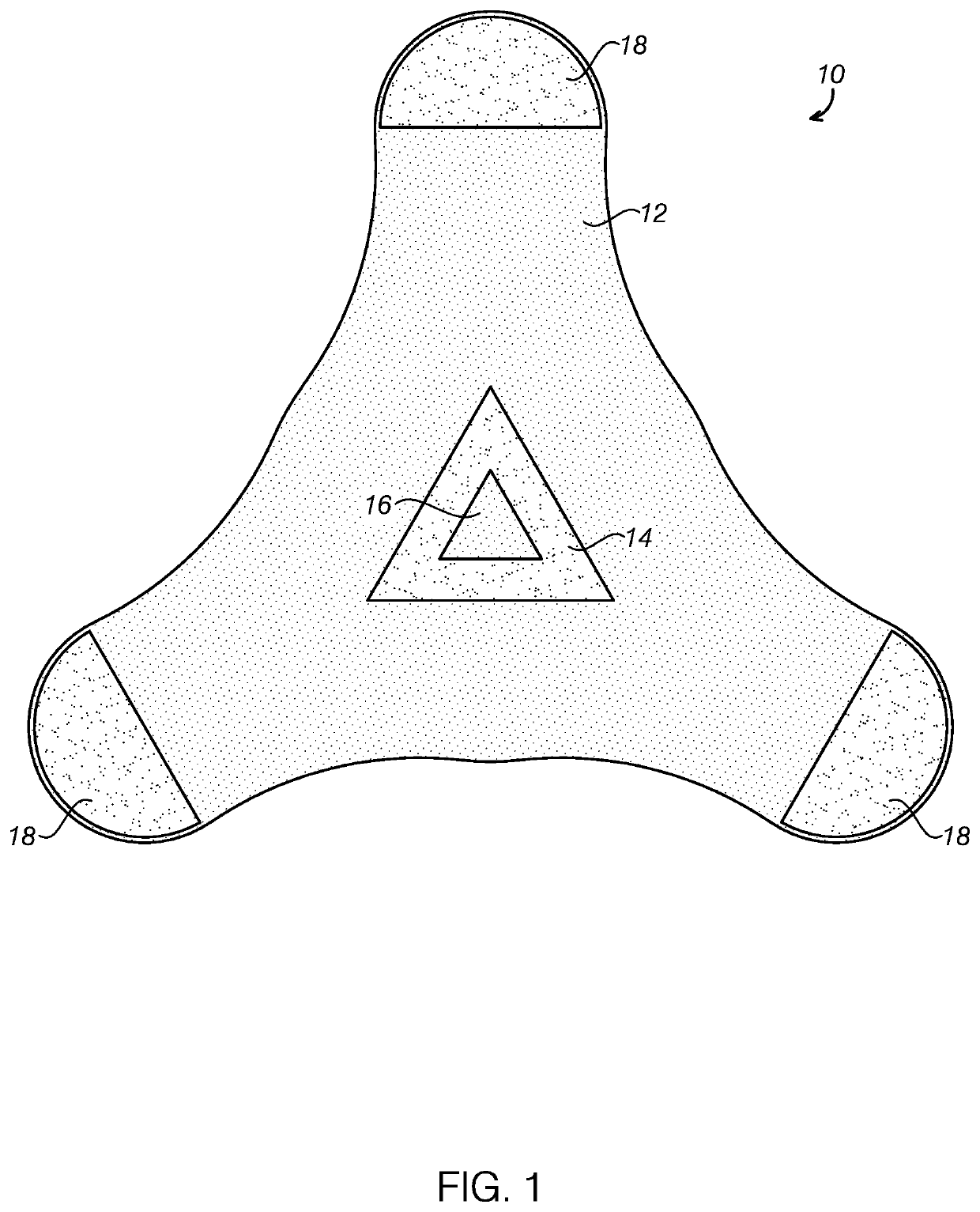
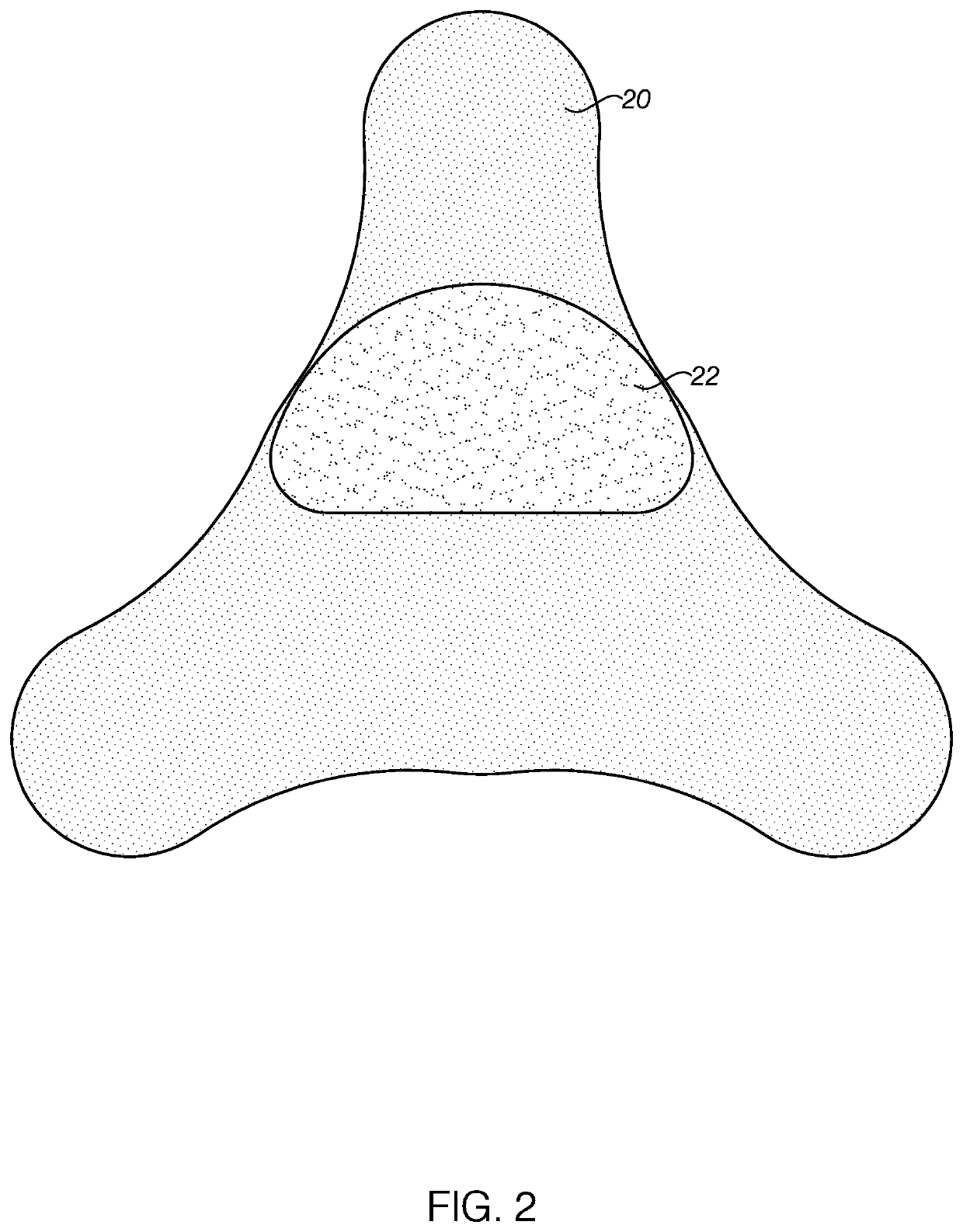
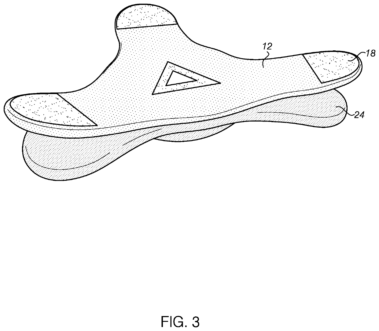
[0013]In some embodiments, a sensor area of the wearable that needs contact with the skin or placement on a specific spot, provided that such a sensor is needed, has a flat circular area around it. Further still, ideally the wearable should be flexible to allow contouring with the body as it moves. A corresponding wearable mount (also referred to as adhesive layer) has a ring of adhesive corresponding to the designated flat portion of the wearable. This adhesive can be a high strength adhesive and bonds the adhesive layer to the wearable, i.e., does not contact the skin. The area in the center of the designated area of the adhesive layer can be a hole allowing sensors or other such device to contact the skin. The rest of the adhesive layer on the side of the wearable does not stick to the wearable. The skin side of the adhesive layer then has a spot of easy to remove adhesive at each point. For example, a triangular shape would have three spots, a four sided layer may have 4 spots, and the like. Additionally, the adhesive layer can be made from material with sufficient stretch to suit the movement of the body but contains memory allowing it to shrink. For example, if the adhesive layer is attached to the chest area, as someone bends forward using abdominal muscles, the points of the adhesive layer will get closer as the skin contracts, then bending outward may cause the chest area to expand, expanding the adhesive layer with it. Throughout this motion, the skin is not restricted by the reduced elasticity of the wearable, thus reducing the risk of the wearable being uncomfortable. Where the wearable is flexible, the changes in body contour is further accommodated. If a flexible wearable or fixed wearable is attached to the body, as the body moves, the skin stuck to the wearable is forced to shift or pull with the movement. This results in the wearable getting undone. Here, the current market solutions are to employ very strong adhesives or large adhesives covering a wearable. With this embodiment of the present invention, as the adhesive layer can stretch with the skin, easy to peel off adhesives can be used, which is important for long term use of wearables, thus reducing skin damage. With the present invention, as the skin moves around, the wearable “floats” on the wearable mount, reducing the discomfort.
[0014]In some embodiments, either incorporated on the wearable or attached as a layer, there is a layer of material that has a higher elasticity than the wearable and, to the extent of possible, skin movement. The wearable side of the adhesive layer can now connect with the wearable on many more points. This provides benefits such as accommodating many sensors, heavier wearables, wearable use under rigorous settings, and the like. So in this use case, as the skin moves, the highly elastic layer of the wearable moves to suit it thereby allowing the skin to move unrestricted thus reducing the discomfort. Again, both restricted and flexible wearables could be used.
[0015]In some embodiments, the wearable has all of the necessary contacts on the skin side surface of the wearable, flush with it. Ordinarily, these contacts could touch the skin or moisture could run across them. By pairing and using the wearable only with a suitable adhesive layer, the adhesive layer covers the ports and insulates the ports from the skin. Additionally, adhesive rings can seal the ports, blocking moisture from penetrating to it and / or moving between contacts. The adhesive can be removed when the wearable is placed for charging, thus exposing the low power contacts. Before attaching for use again, a new adhesive is applied, as is required to reduce skin irritation, and, at the same time, to restore the insulating and isolating properties. The end result is that no additional infrastructure is required to affect these two important safeguards, thereby allowing the wearable to have a small form factor. Additionally, covers for ports of conventional wearables get damaged or lost, rendering the device inoperative. It should be noted that the device could be washed with the adhesive off, as wearables tend to have extensive power management components that could detect these activities and shut off the ports for this activity.
[0016]In some embodiments, the material used on the underside of the wearable be the same as the outer side, or at least compatible with the adhesive used on the underside. This feature allows an adhesive layer to be placed on the outside of the device. What this does is that it facilitates the sticking of any compatible material, such as paper, foil, plastic, or the like, that is configured as a different shape, color, pattern, or the like, on the outer side of the wearable, effectively changing the appearance of the wearable. This step is not possible today as most wearables have adhesives holding the actual wearable in place which cross the top or the top material is made from materials that are silicone based, reducing its ability to retain adhesives on it. Such a feature allows children to stick on paper, or the like, in different shapes, or with characters, or depicting objects, or the like, thereby giving them comfort as they use the device. It is akin to a child wearing an under vest with their favorite character printed on it as it gives them comfort, especially as they face an uncomfortable situation.

Problems solved by technology

This results in the wearable getting undone.

Method used


Image

  • Wearable apparatus
  • Wearable apparatus
  • Wearable apparatus

Examples


Embodiment Construction

[0030]The terminology used herein is for the purpose of describing particular embodiments only and is not intended to be limiting of the invention. As used herein, the term “and / or” includes any and all combinations of one or more of the associated listed items. As used herein, the singular forms “a,”“an,” and “the” are intended to include the plural forms as well as the singular forms, unless the context clearly indicates otherwise. It will be further understood that the terms “comprises” and / or “comprising,” when used in this specification, specify the presence of stated features, steps, operations, elements, and / or components, but do not preclude the presence or addition of one or more other features, steps, operations, elements, components, and / or groups thereof.

[0031]Unless otherwise defined, all terms (including technical and scientific terms) used herein have the same meaning as commonly understood by one having ordinary skill in the art to which this invention belongs. It wi...


PUM


Abstract

A wearable and / or a wearable mount solves many issues presented with conventional wearables and wearable mounts. For example, the wearable mount can be designed with a low ratio of adhesive contact area to wearable mount contact area while providing the capability to collect data and / or dispense medication on one specific spot and, further still, allowing the use of an easy to remove adhesive. This configuration may facilitate free movement of the body even when the wearable mount is attached to the skin. The wearable may have surface contacts, removing the need for ports that could be damaged. The adhesive layer can provide insulation and isolating properties for the contacts while the device is being worn. Finally, the wearable may be a patch-type wearable that allows the appearance of the wearable to be changed without the need for housing changes or other costly solutions.

Description

BACKGROUND OF THE INVENTION1. Field of the Invention[0001]One or more embodiments of the invention relates generally to wearable apparatus. More particularly, the invention relates to physical design features and specifications for a wearable intended for use on a human body and other applicable mammalian bodies. The wearable may or may not be equipped with sensors to collect information from the body either as contact or close proximity non-contact with or without position specific, zero or minimal drift constraints.2. Description of Prior Art and Related Information[0002]The following background information may present examples of specific aspects of the prior art (e.g., without limitation, approaches, facts, or common wisdom) that, while expected to be helpful to further educate the reader as to additional aspects of the prior art, is not to be construed as limiting the present invention, or any embodiments thereof, to anything stated or implied therein or inferred thereupon.[000...

Claims


Application Information

Patent Timeline
Patent Type & Authority Patents(United States)
IPC IPC(8): A61B5/00G01D11/30A61B5/296
CPCG01D11/30A61B5/6832A61B5/6833A61B2562/164
Inventor DWARIKA, JAREDSAMJITSINGH, SHARON
Owner HEALTH CARE ORIGINALS INC
Learn More