Hybrid cordless cap tool

a cordless cap and tool technology, applied in the field of construction tools, can solve the problems of increasing the weight of the tool, reducing the efficiency of the construction process, so as to achieve efficient harnessing and conserved energy

Active Publication Date: 2021-03-30
NAT NAIL
View PDF63 Cites 0 Cited by
  • Summary
  • Abstract
  • Description
  • Claims
  • Application Information

AI Technical Summary

Benefits of technology

[0015]The current embodiments provide a tool and method having functionality that previously was unachievable. The tool is sustainable, harvesting and utilizing mechanically input energy, as well as energy from a rechargeable battery. The mechanically input energy can be stored in a biasing element and used by the bell crank and other components to advance caps and fasteners. The power source and its stored energy can be conserved and utilized primarily only to advance a fastener in the nose assembly through a cap. The power source thus need not be consumed to move the caps and fasteners in such a construction. Where the power source is a rechargeable battery, it can be recharged multiple times to advance many fasteners on a job site or during a construction project. The power is not consumed in such a case by too many functions. The movement of the tool also is efficiently harnessed to harvest input energy and forces to move the caps and fasteners.

Problems solved by technology

While these tools are powerful and durable, they are many times unwieldy because they always have an air hose attached to the tool.
This adds weight to the tool.
In addition, users can many times cut or damage the air hose on a job site, which then requires repair of the hose to use the tool, which in turn leads to down time and added labor costs.
While it frees the tool from an unwieldy air hose, this tool can have issues as well.
For example, in some cases, where the tool is not swung hard enough, the weight might not properly advance a cap or a nail.
In other cases, when the tool is dropped, it might inadvertently jam.
In yet other cases, where improper caps are used, the tool might require a different swing stroke to adequately drive the nail and cap.

Method used


Image

  • Hybrid cordless cap tool
  • Hybrid cordless cap tool
  • Hybrid cordless cap tool

Examples


Embodiment Construction

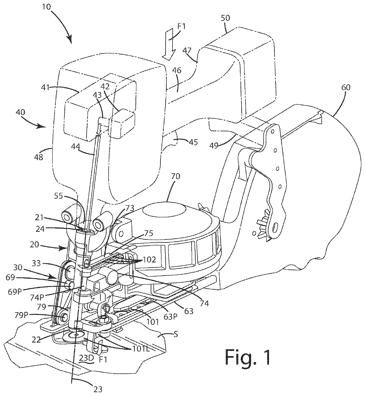
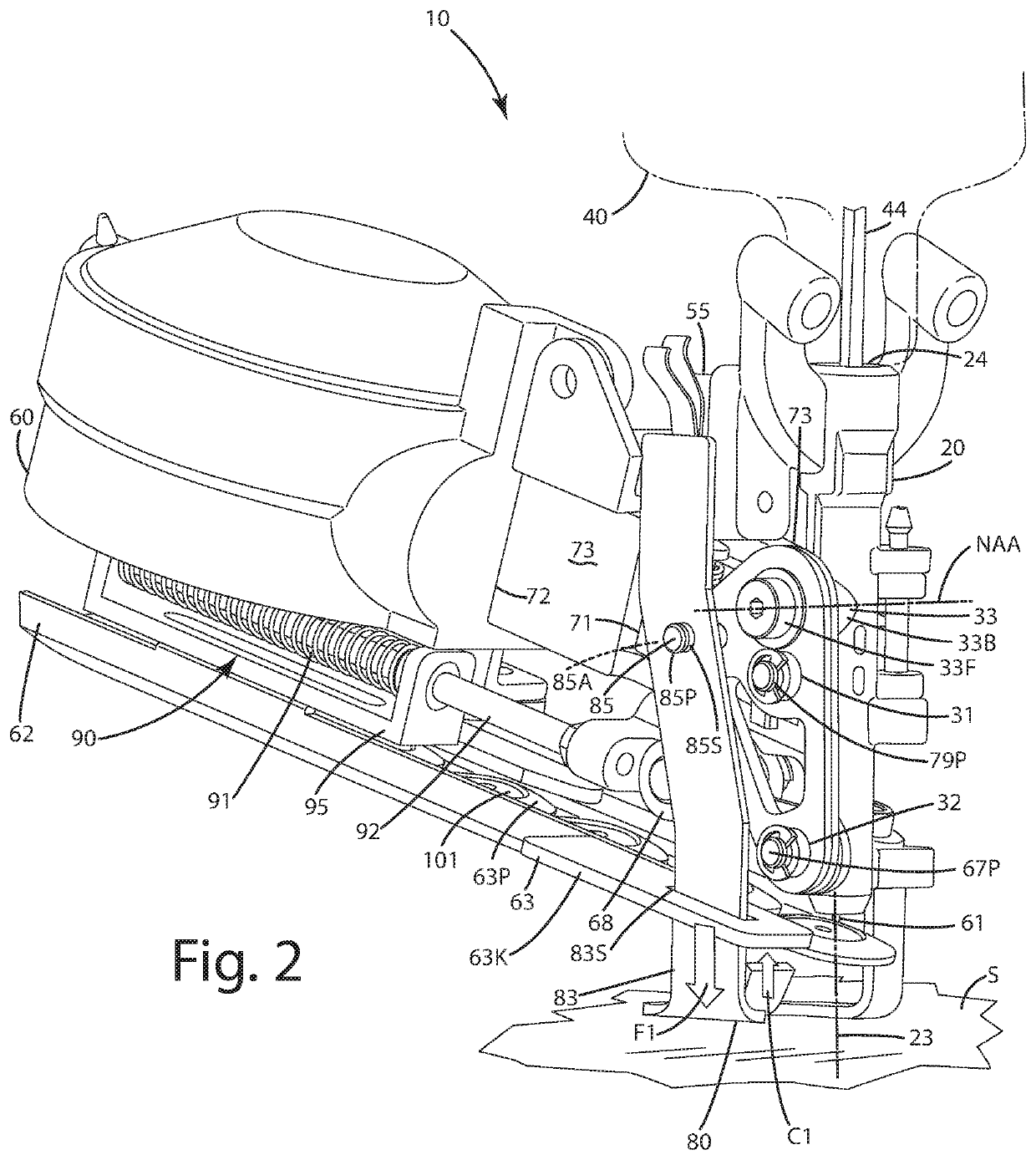
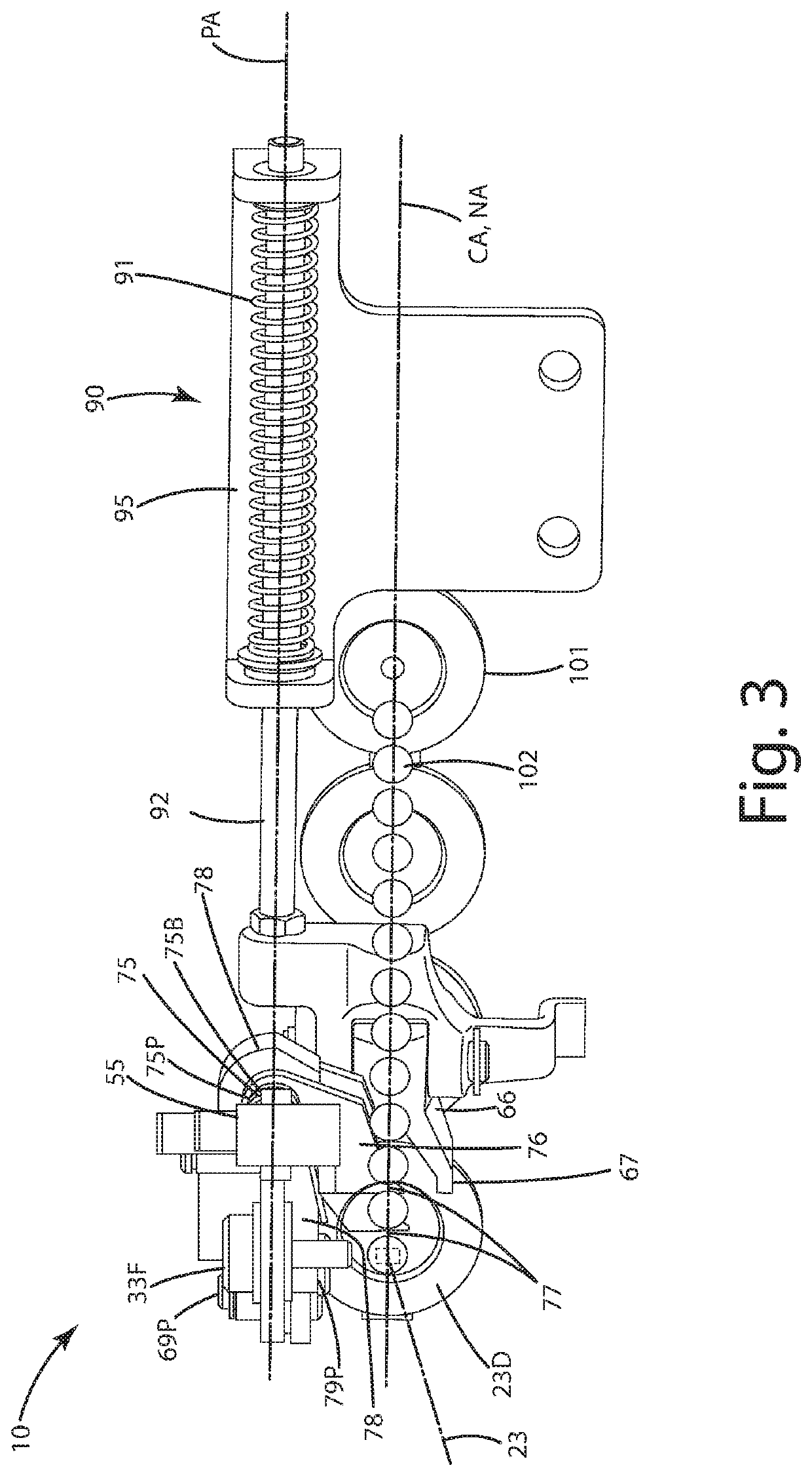
[0028]A current embodiment of a tool of a current embodiment is shown in FIGS. 1-9 and generally designated 10. The tool 10 can be utilized to feed fasteners 101 and caps 102 sequentially toward a nose assembly 20 of the tool, in particular, into the line of a fastener driving path 23 that intersects a fastener driving station 23D. The movement of the fasteners and the caps is provided via the bell crank 30 of the tool 10 that uses mechanical energy input by movement of the tool 10 and stored in a biasing element. The bell crank uses that mechanical energy to move elements that engage the fasteners and the caps respectively and move them toward a discharge station 23, and more particularly, into the fastener driving path 23. When a particular fastener and a cap, for example, a leading fastener 102L and a leading cap 101L are disposed in the fastener driving path 23, the driving unit 40 of the tool 10 can be powered via a power source 50 that is joined with the tool. The power source...


PUM


Abstract

A construction tool and method for use for administering a fastener and an associated cap to secure fabrics, paper, sheets, and / or panels to a substrate is provided. The tool can be a hybrid tool that utilizes a) energy stored in a spring, the energy harvested upon engagement of the tool with a surface, to move a cap and / or a fastener to an advancement station, and b) energy stored in a power source, such as a battery, to advance the fastener through the cap and apply the fastener / cap combination to a substrate. The hybrid tool can utilize both energy harvested from mechanical motion and energy stored in an onboard power source to function. A related method of using the tool is provided.

Description

BACKGROUND OF THE INVENTION[0001]The present invention relates to a construction tool adapted to apply caps and fasteners, and more particularly to a tool that drives a fastener through a cap to fasten the cap to a substrate.[0002]In the construction industry, certain tools have been developed that are used to secure fabric, sheet material, and / or panels (collectively “panels”) to an underlying substrate, such as a wall, a roof or other surface. To adequately secure the items, a combination of a nail or staple with a flat, rather large diameter cap is used. The nail is driven through the cap, and that combined unit engages the panel, with the nail piercing the panel and entering the substrate. The larger diameter cap increases the surface area of the nail / cap combination engaging the panel to better secure the panel to the substrate.[0003]Conventional tools that simultaneously apply a nail and a cap come in two primary forms. One of those forms is a pneumatically operated tool. This...

Claims


Application Information

Patent Timeline
Patent Type & Authority Patents(United States)
IPC IPC(8): B25C7/00B25C1/06B25C1/00B25C5/15B25C5/16
CPCB25C1/06B25C1/003B25C1/008B25C7/00B25C5/15B25C5/1693
Inventor VANDENBERG, ROGER A.
Owner NAT NAIL
Why Eureka
Try Eureka