Trailing edge assembly

a technology of wind turbines and rotor blades, which is applied in the direction of motors, passive/reactive control, engine fuction, etc., can solve the problems of rotor blades subject to aerodynamic loads, rotor blades and wind turbine supporting structures are fatigued, and atmospheric wind is rarely steady

Active Publication Date: 2021-04-06
SIEMENS GAMESA RENEWABLE ENERGY AS
View PDF34 Cites 9 Cited by
  • Summary
  • Abstract
  • Description
  • Claims
  • Application Information

AI Technical Summary

Benefits of technology

[0007]An aspect relates to provide a more economical and straightforward way of adjusting the flap angle of a wind turbine rotor blade.

Problems solved by technology

During operation of a wind turbine, its rotor blades are subject to aerodynamic loads.
However, atmospheric wind is rarely steady over long intervals, and is more usually irregular with gusts and turbulence leading to fluctuations in loading.
The changes in loading as the rotor blades pass through these regions result in fatigue loads on the rotor blades and the wind turbine supporting structure.
A problem with the corrective measures described above—i.e. corrective measures limited to adjusting the blade pitch angle—is that they are not quick enough to prevent excessive loading by gusts, turbulent wind fields or wakes.
Therefore, even though pitch control is effective in maintaining rotor speed and turbine power, the ability to counteract rapid load variations is limited.
Additional effort and cost is associated with the need for a dedicated flap control system in addition to the pitch control system.
While these systems allow precise adjustment of the trailing edge geometry in response to fluctuating aerodynamic loads, they suffer from a number of disadvantages.
For example, any components must be installed within the blade so as not to affect the airflow over the blade, but it is difficult and expensive to install and service complex actuator systems inside wind turbine rotor blades.
Furthermore, any moving parts are prone to failure.
These actuator systems must be serviced, but their location in an outboard region of the blade interior makes such maintenance procedures difficult and costly.
Joints, hinges or connectors at the outside of an adaptive flap system may be damaged by ice build-up in cold conditions.
Furthermore, active components usually require the use of feedback sensors, which are also subject to the drawbacks mentioned above.
Similarly, if the angle of attack decreases—for example because of natural variations in the wind, or because of operating conditions of the wind turbine—the thickness of the boundary layer over the airfoil will decrease, the velocity of the airflow in the boundary layer at a given height above the surface will increase, resulting in an increase in stagnation pressure in the volume adjustable chamber, and this will inflate accordingly.
However, it may not be possible to completely prevent water from entering the tube and the volume adjustable chamber.
However, there may be differences in this relative velocity over the rotor swept area, caused for example by differences in relative wind speed arising from yaw error, wind shear, etc.

Method used


Image

  • Trailing edge assembly
  • Trailing edge assembly
  • Trailing edge assembly

Examples


Embodiment Construction

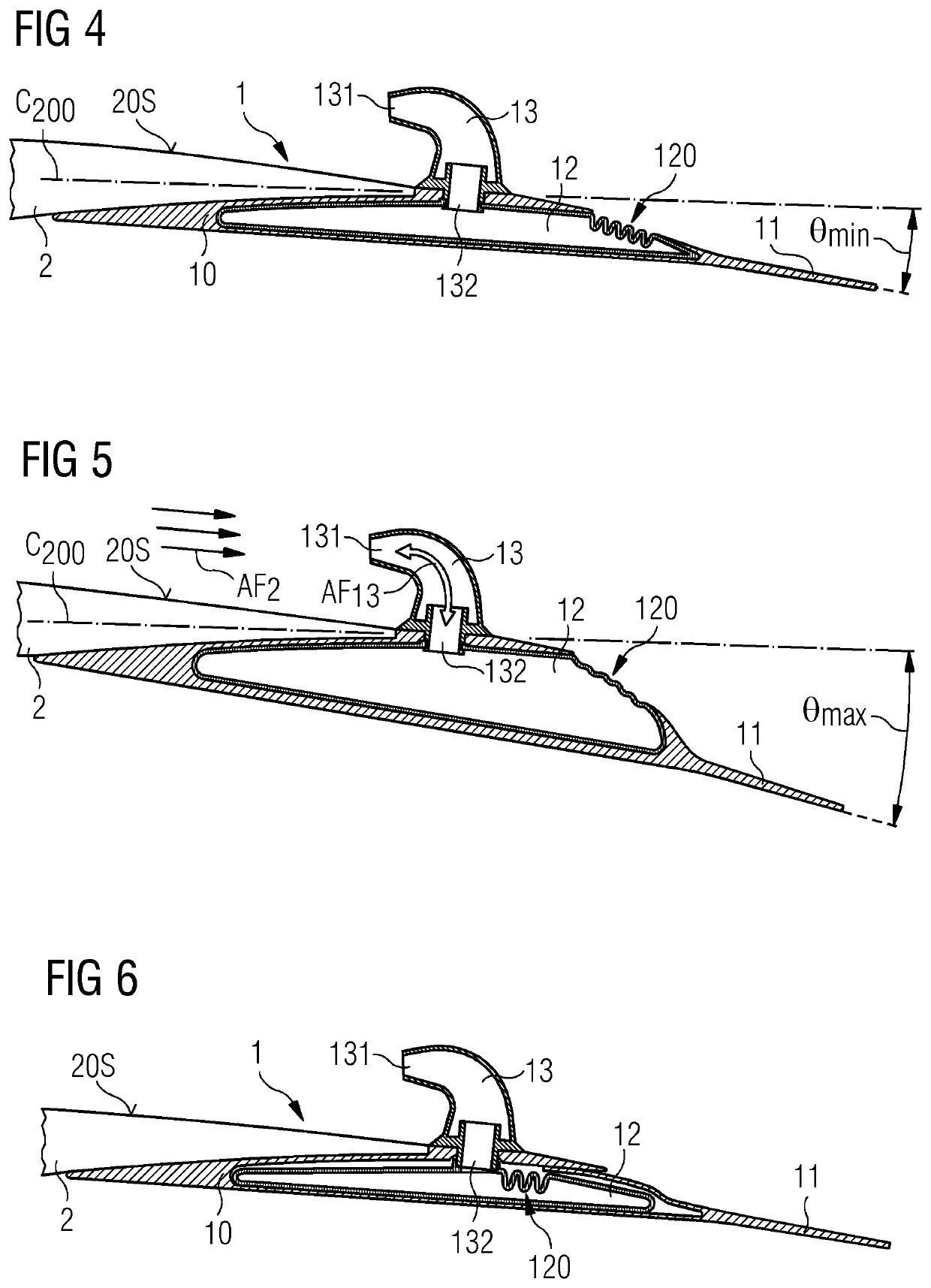
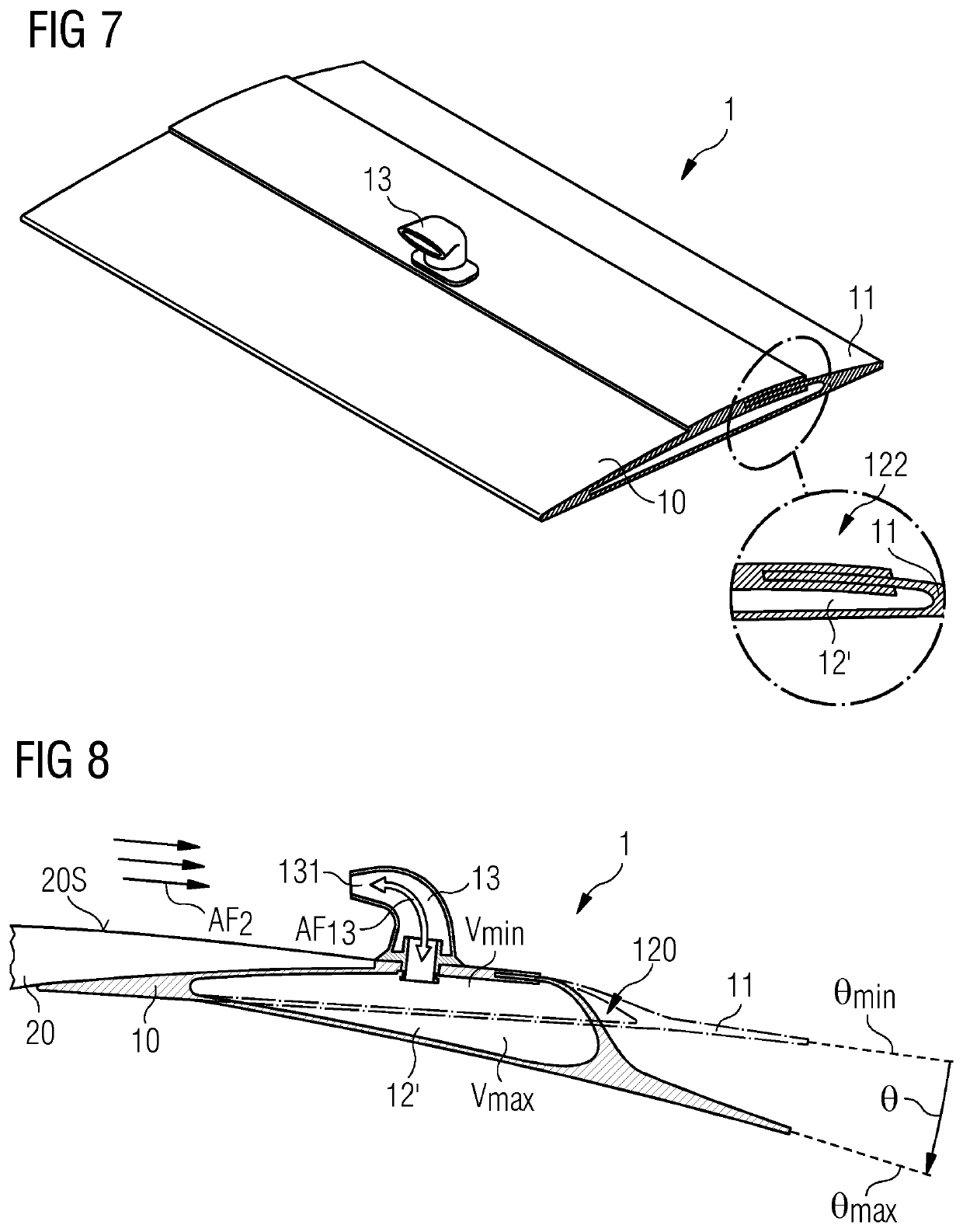
[0050]FIG. 1 shows a cross-section through an embodiment of the inventive trailing edge assembly 1 or passive flap system 1. The passive flap system 1 has a mounting portion 10 shaped for mounting to an airfoil region of a rotor blade, and a flap portion 11 that is flexibly connected to the mounting portion 10. In all the embodiments described herein, the flexible connection is achieved by using a suitably elastic material. The material “hinge” allows a flap angle subtended between the mounting portion 10 and the flap portion 11 (indicated in FIG. 5 and FIG. 8) to be altered smoothly. In this embodiment of the inventive passive flap system, an inflatable hose 12 or balloon-like body 12 is arranged between the mounting portion 10 and the flap portion 11. A tube 13 extends through the mounting portion 10 and opens into the inflatable hose 12. The tube has an outer orifice 131 arranged to face into an airflow, and an inner orifice 132 arranged to face into the interior of the inflatabl...


PUM


Abstract

Provided is a trailing edge assembly of a wind turbine rotor blade, which includes a mounting portion; a flap portion flexibly connected to the mounting portion so that a flap angle subtended between the mounting portion and the flap portion can be altered; a volume adjustable chamber arranged between the mounting portion and the flap portion and realised to alter its volume between a minimum volume associated with a minimum flap angle and a maximum volume associated with a maximum flap angle; and at least one tube to face into an airflow passing over the airfoil region of the rotor blade, and an inner orifice arranged to face into the interior of the volume adjustable chamber such that an airflow between the outer orifice and the inner orifice alters the volume of the volume adjustable chamber. Embodiments of the invention further describe a wind turbine rotor blade.

Description

CROSS-REFERENCE TO RELATED APPLICATIONS[0001]This application claims priority to EP Application No. 18153823.2, having a filing date of Jan. 29, 2018, the entire contents of which are hereby incorporated by reference.FIELD OF TECHNOLOGY[0002]The following relates to a trailing edge assembly of a wind turbine rotor blade; and a wind turbine rotor blade comprising at least one such trailing edge assembly.BACKGROUND[0003]During operation of a wind turbine, its rotor blades are subject to aerodynamic loads. It is usual to adjust the angle of attack and / or the rotational velocity of the rotor blades in order to keep the blade loading at an acceptable level while aiming to keep the wind turbine power output at the desired level. This is done by adjusting the rotor blade pitch angle by means of a pitch drive at the interface between rotor blade and hub. The angle of attack and / or rotational velocity may be reduced as needed, for example by adjusting the rotor blade pitch angle by a suitabl...

Claims


Application Information

Patent Timeline
Patent Type & Authority Patents(United States)
IPC IPC(8): F03D7/02F03D1/06
CPCF03D7/0232F03D1/0641F03D1/0675F03D1/0683F05B2240/2211F05B2240/301F05B2240/311F05B2250/14F05B2250/183F05B2270/402F03D80/00F05B2260/96Y02E10/72F05B2240/3052
Inventor AKAY, BUSRAENEVOLDSEN, PEDER BAYGONZALEZ, ALEJANDRO GOMEZ
Owner SIEMENS GAMESA RENEWABLE ENERGY AS
Why Eureka
Try Eureka