Arrangement for Holding a Substrate in a Material Deposition Apparatus

a technology for arranging substrates and material deposition, which is applied in the direction of electrical devices, ion implantation coatings, coatings, etc., can solve the problems of poor product quality, no longer precise boundaries of material deposited in openings, and shadow masks that do not maintain satisfactory close contact with substrates. , to achieve the effect of straightforward and reliabl

Active Publication Date: 2012-07-12
DOLYA HOLDCO 5 LTD
View PDF11 Cites 10 Cited by
  • Summary
  • Abstract
  • Description
  • Claims
  • Application Information

AI Technical Summary

Benefits of technology

[0008]Therefore, it is an object of the invention to provide a straightforward and reliable way of ensuring precise material deposition on a substrate in a material deposition process.
[0010]An advantage is that the shadow mask is supported essentially over its entire area during the material deposition process. Therefore, even though the shadow mask has a very delicate structure, with a high proportion of openings or negative area, it is effectively supported by the support structure and prevented from parting from the substrate during the vapour deposition process. The support structure effectively acts to hold the shadow mask flat, so that the substrate is in contact with the shadow mask over its entire surface. An additional advantage of the arrangement is that, with appropriate choice of material for the support structure, this can act as a thermal shield to ‘absorb’ heat, thus reducing the degree to which the shadow mask is heated. Finally, because the weight of the shadow mask can be borne by the support structure, the shadow mask itself can be made of a very thin material e.g. a thin sheet, 0.05 mm to 0.3 mm in thickness. Using this arrangement, therefore, material can be deposited on the substrate within very precisely defined regions.
[0011]This arrangement therefore allows the production of high-quality semiconductor devices in an economical and straightforward manner.
[0014]The support structure can be designed in any shape suitable to support the shadow mask. In particular, the support structure can comprise a support mask or support bars. The support bars can be shaped in the form of a frame surrounding the perimeter of the shadow mask. The support bars can additional comprise bars extending from the outer periphery of the support structure in the direction of the centre of the support structure in order to provide additional support to the central parts of the shadow mask. The support bars can also comprise crossing bars in order to enhance the stability and stiffness of the support structure and in order to provide more support to the shadow mask. Furthermore the number of openings in the support structure does not have to correspond to the number of openings in the shadow mask. For example the number of openings in the support structure can be lower than the number of openings in the shadow mask. In this case, one big opening in the support structure can correspond to at least two smaller openings in the shadow mask. The shape of the openings of the support structure can be different to the shape of the openings in the shadow mask. For example a smaller square shaped opening in the shadow mask can correspond to a bigger round-shaped opening in the support structure.
[0018]It has been pointed out above that the material deposited on the substrate should ideally have a homogenous layer thickness and precisely defined edges, particularly when the end-product is intended for use in applications such as displays, where the sharpness of a rendered image may be influenced to a great extent by the quality of the material deposition. The sharpness of the edges of the regions of material deposited on the substrate is governed to a large extent by the depth of the mask through which the material must pass before arriving at the substrate. The thinner the mask, the sharper will be the edges of the deposited regions. Therefore, in a further preferred embodiment of the invention, a surround opening of the support mask is larger than the associated deposition opening of the shadow mask. In this way, the support mask does not add to the thickness of the shadow mask at the edges of the deposition openings, while still being able to bear the weight of the shadow mask. In a further embodiment of the invention, the support mask may have bevelled or slanted edges, preferably with chamfered corners, so that the support mask does not in any way hinder the vapour from arriving at the deposition openings.
[0019]To ensure optimal support of the shadow mask while at the same time ensuring exact deposition of the material in the shadow mask openings, the shadow mask is preferably positioned relative to the support mask such that a deposition opening of the shadow mask is positioned over a corresponding surround opening of the support mask, and such that the deposition opening of the shadow mask lies within the corresponding, larger, surround opening of the support mask. For example, the openings of a support mask for a vapour deposition step in an OLED manufacturing process may be larger all round by up to a few millimetres than the openings in the shadow mask. This arrangement ensures that the support mask does not in any way adversely affect the precision of the material deposition process.

Problems solved by technology

However, problems arise when the shadow mask does not maintain a satisfactory close contact with the substrate during the deposition process.
When the shadow mask no longer adheres to the substrate over its entire area, the boundaries of the material deposited in the openings are no longer precisely defined, and a poor product quality may be the result.
Uneven or smudged edges of deposited regions are unacceptable in a product such as an OLED display, and such poor quality can result in high costs.
However, since material deposits accumulate on the shadow mask, this must eventually be replaced.
A shadow mask that is simply attached to the frame by means of clamps can relatively easily be removed and replaced, but a welded shadow mask requires an additional effort in its removal by mechanical means, and the frame surface may also need to be milled before the next shadow mask is welded into place.
Therefore, such an approach is relatively expensive.
Furthermore, since most OLEDs require multiple layers to be built up in consecutive deposition steps, use of a welded mask may be particularly inconvenient.
However, a shadow mask used in the manufacture of OLEDs for lighting purposes generally has a high proportion of openings in its overall surface area, also termed ‘negative area’, so that the application of a lateral tensile force is of limited advantage.
Also, with this approach, it is difficult to ensure that the shadow mask and substrate remain in position relative to one another.
It may happen that the shadow mask shifts or moves to one side during transport or deposition, resulting in unacceptable “smudged” material layers.
However, for products such as displays, in which material is deposited to form OLED pixel regions, any foreign particles that adhere to the substrate—usually by falling onto the substrate—may result in a visible defect.

Method used


Image

  • Arrangement for Holding a Substrate in a Material Deposition Apparatus
  • Arrangement for Holding a Substrate in a Material Deposition Apparatus
  • Arrangement for Holding a Substrate in a Material Deposition Apparatus

Examples


Embodiment Construction

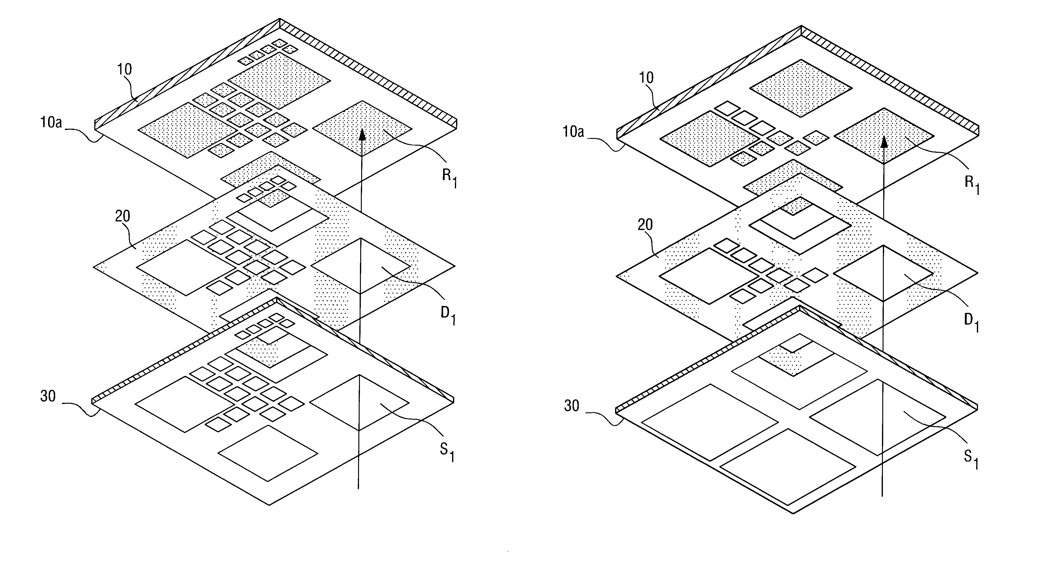
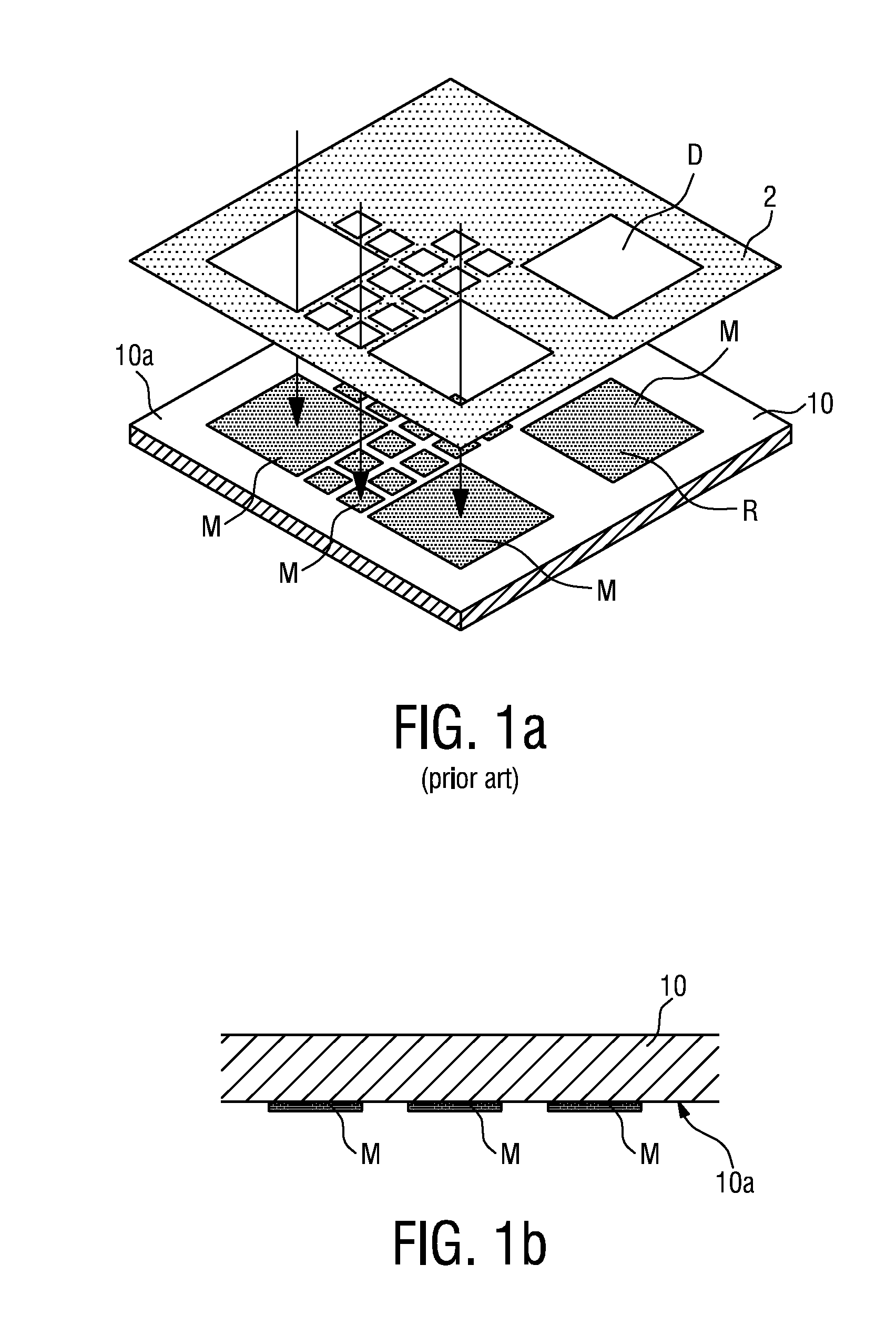
[0039]FIG. 1a shows the relationship between a substrate 10, upon which material is to be deposited, and a shadow mask 2. The material is to be deposited on a deposition side 10a of the substrate 10. The shadow mask 10 has a number of cut-outs or openings, and each opening is associated with a corresponding region on the deposition side 10a of the substrate 10. For example, deposition opening D of the shadow mask 2 is associated with the corresponding region R on the substrate 10. For the sake of clarity, only a few openings are shown. Evidently, the openings can be distributed over the entire area of the shadow mask, and they can be of any required shape.

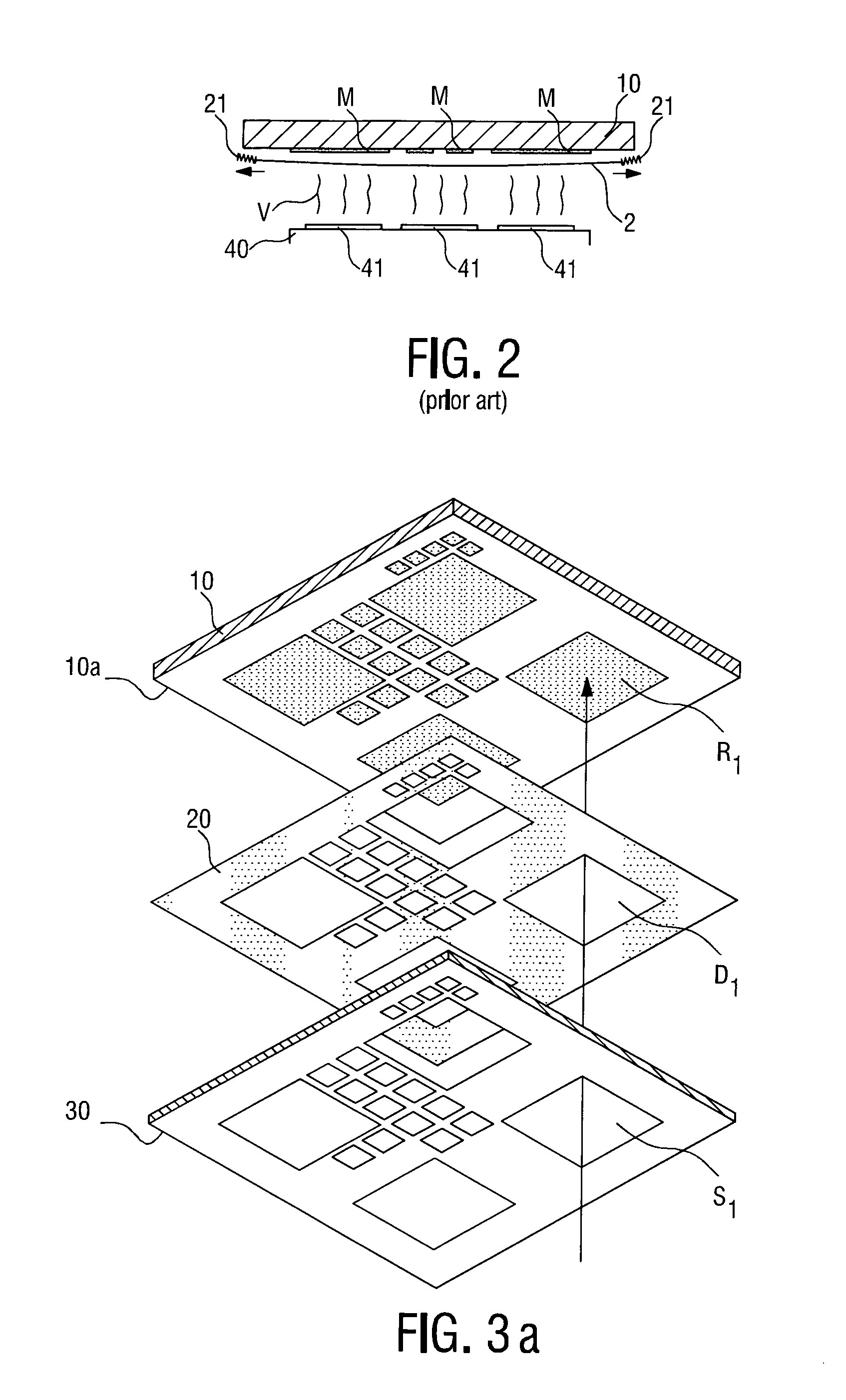
[0040]In OLED manufacture, as mentioned already, material is often deposited from below in a vapour deposition procedure. FIG. 1b shows a cross-section of a substrate 10 with a deposition side 10a upon which material M has been deposited from below. Usually, the thickness of the material layer is only in the region of nanometres, b...


PUM

PropertyMeasurementUnit
thicknessaaaaaaaaaa
thicknessaaaaaaaaaa
thicknessaaaaaaaaaa

Abstract

An arrangement (1) for holding a substrate (10) in a material deposition apparatus, which substrate (10) has a deposition side (10a) upon which material (M) is to be deposited, and which arrangement (1) comprises: a shadow mask (20) comprising a number of deposition openings (Di); a support structure (30) comprising a number of surround openings (Si); and a support structure holding means (6) for holding the support mask (30) and / or a substrate holding means (5) for holding the substrate (10), such that the support structure (30) is on the same side as the deposition side (10a) of the substrate (10), and the shadow mask (20) is positioned between the substrate (10) and the support structure (30) such that at least one deposition opening (Di) of the shadow mask (10) lies within a corresponding surround opening (Si) of the support structure (30).

Description

RELATED APPLICATIONS[0001]This is a U.S. national stage of application No. PCT / IB2010 / 051356, filed on Mar. 29, 2010.[0002]This application claims the priority of European application no. 09157249.5 filed Apr. 3, 2009 and 10154410.4 filed Feb. 23, 2010, the entire contents of both of which are hereby incorporated by reference.FIELD OF THE INVENTION[0003]The invention describes an arrangement and method of arranging a substrate and a shadow mask in a material deposition apparatus.BACKGROUND OF THE INVENTION[0004]In some semiconductor manufacturing processes, a vapour deposition step is necessary in order to deposit matter—organic or inorganic—on a substrate. In some processes, the matter must be deposited within precisely defined areas on the substrate. To simplify the deposition process, a shadow mask is usually applied to one side of the substrate, and cut-outs or openings in the shadow mask define the regions in which matter will be deposited. It is usually a requirement that the ...

Claims


Application Information

Patent Timeline
Patent Type & Authority Applications(United States)
IPC IPC(8): H01L51/56B05D3/12B05C13/02
CPCC23C14/042Y10T29/41C23C14/50C23C14/04C23C14/22C23C14/54
Inventor KRIJNE, JOHANNESEILING, ERWINHOHAUS, KARL-HEINZGOERGEN, WOLFGANGLOVICH, ANDREASPHILIPPENS, MARCSCHEICHER, RICHARDFISCHER, ANSGARMUELLER, MARTIN
Owner DOLYA HOLDCO 5 LTD
Why Eureka
Try Eureka