Eureka AIR delivers breakthrough ideas for toughest innovation challenges, trusted by R&D personnel around the world.

Current controlling device

a current control and control device technology, applied in the direction of variable inductance, normal-superconductive switchable devices, inductances, etc., can solve the problems of requiring maintenance and replacement of constituent parts, and affecting the operation of the distribution system. , to achieve the effect of replacement, and reducing the cost of maintenan

Active Publication Date: 2021-04-06
ROLLS ROYCE PLC
View PDF7 Cites 0 Cited by
  • Summary
  • Abstract
  • Description
  • Claims
  • Application Information

AI Technical Summary

Benefits of technology

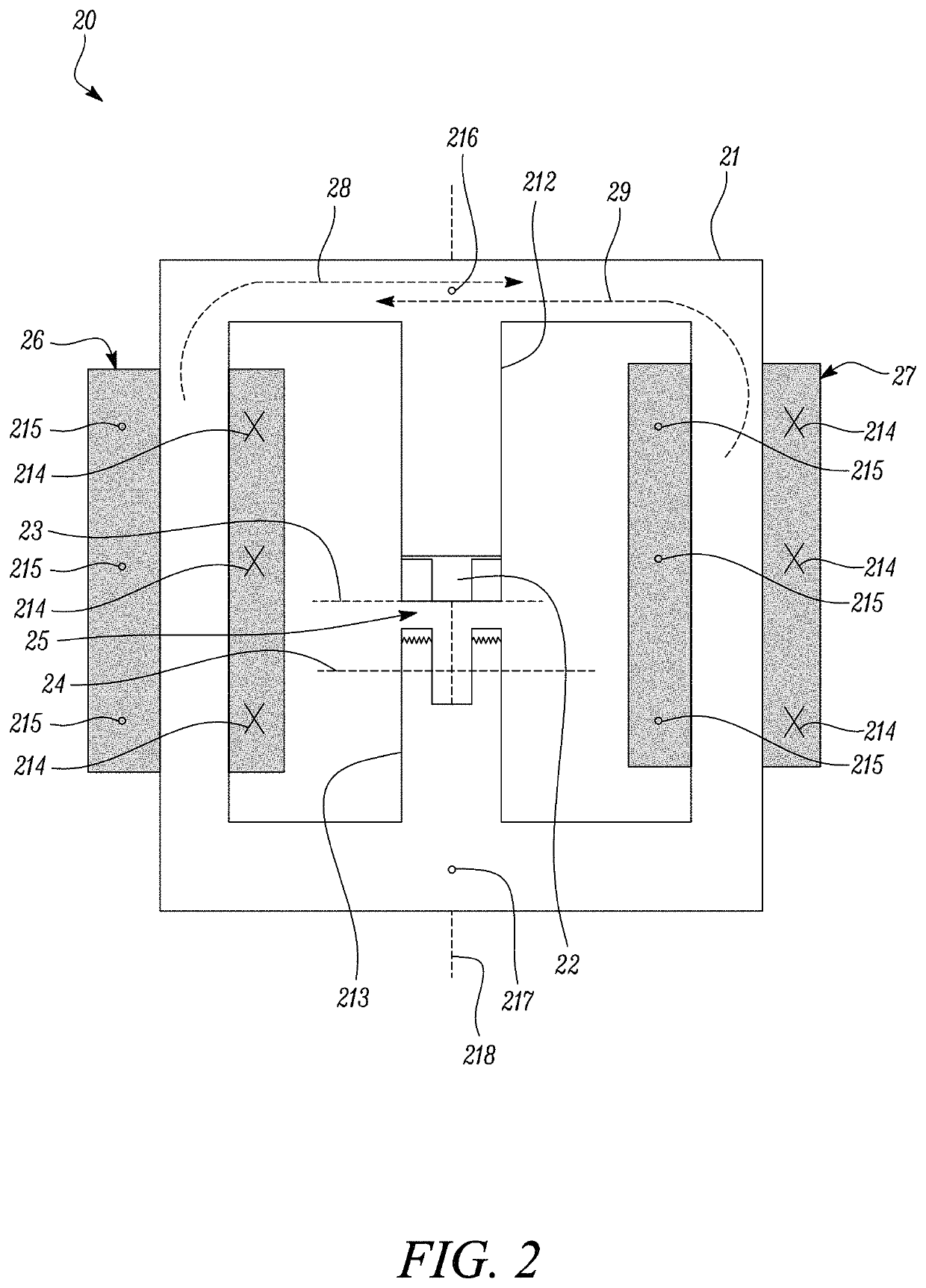
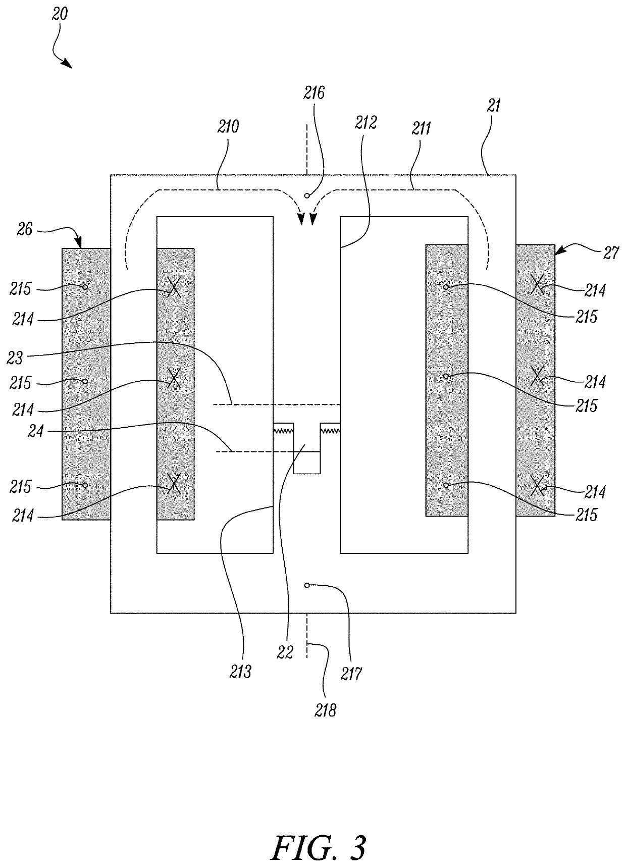
[0017]By controlling the amount of impedance experienced by the power distribution system, the device can be used as a fault current limiter having a simpler and more compact design than prior art arrangements. Furthermore, the ability to control the impedance experienced by current through the device allows greater versatility of operation during normal current modes in that the device can also be used as a differential mode filter, a common mode filter or a variable inductor. This has further size and compactness benefits compared to hypothetical arrangements in which these devices are provided separately.
[0018]Furthermore, activating the fault current limiter requires moving the bridge element to a fully closed position. This mechanical response provides faster activation of the fault current limiter in response to detecting that a fault condition exists in the power distribution system. This is particularly true compared to hypothetical fault current limiters that take time to activate, e.g. due to the need for the core to “quench” or become unsaturated. This is advantageous in that the larger fault current would be applied in the main distribution network for a shorter amount of time.
[0019]Furthermore, the device provides an impedance to current by utilising the current in the electrical power system itself. This is more practical and economical than hypothetical arrangements in which the fault current limiter requires an external source of power in order to achieve the same result.
[0035]switching the device to operate in an active mode of operation by causing the bridge element to be moved to the fully-closed position, such that a net magnetic field is sustained across the core.

Problems solved by technology

A known problem with electrical power systems is that the distribution system can occasionally experience faults, which may be the result of crossed or downed distribution lines, for example.
Faults in the distribution system can cause an excessive current (which is to be referred to herein as “overcurrent” or “fault current”) to flow through the wider electrical power system, which is particularly problematic to upstream critical loads that often become damaged as a result.
A problem in such systems, however, is that they are bulky in size (e.g. in that they have a parallel circuit) and often require servicing and replacement of constituent parts after a fault occurs.

Method used


Image

  • Current controlling device
  • Current controlling device
  • Current controlling device

Examples


Embodiment Construction

[0046]In the Figures, like reference numerals are used to refer to like features, where appropriate.

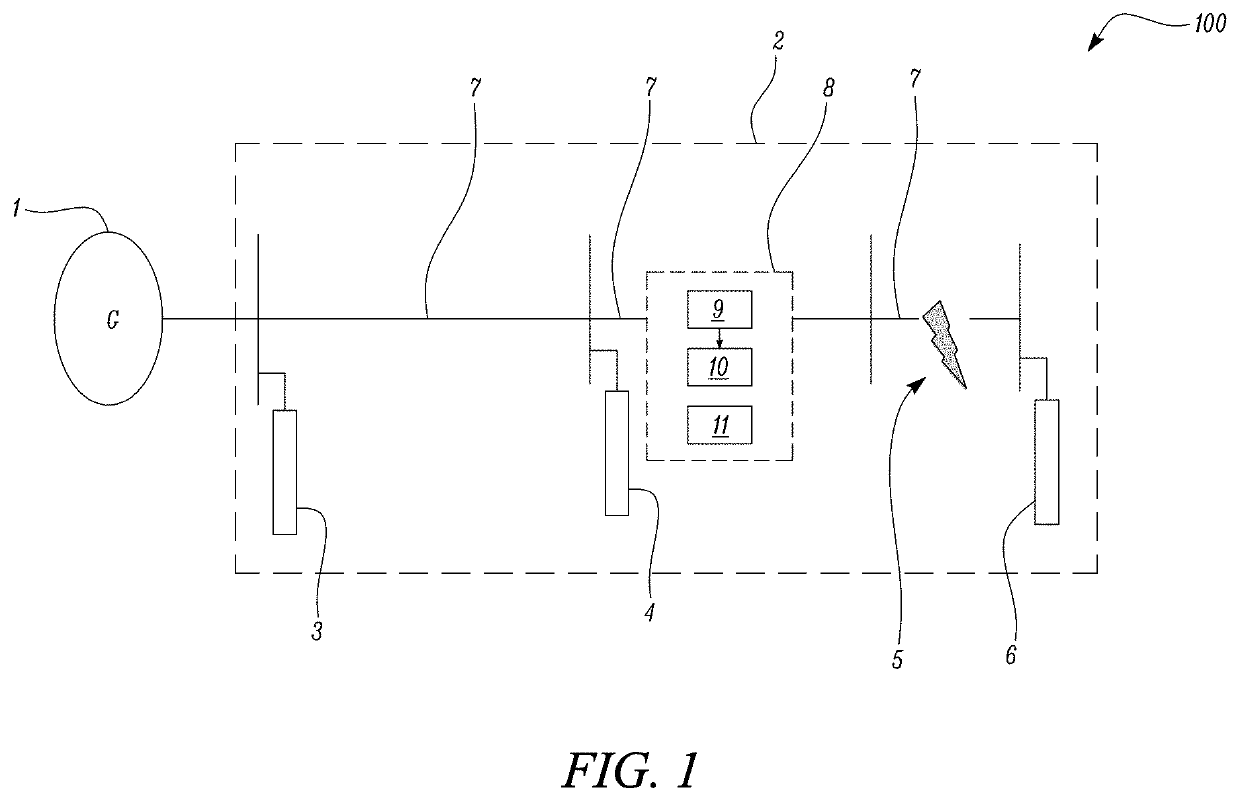
[0047]With reference to FIG. 1, which is a line diagram of an electrical power system, there is provided an electrical power system 100 which comprises a generator set 1 that produces electrical power and a power distribution system 2 that feeds the power to nearby electronic components of the power distribution system 2.

[0048]In the example of FIG. 1, the generator set 1 is driven by a synchronous generator to generate alternating-voltage (AC) for the distribution system 2. However, the generator set 1 may be driven by any suitable rotary drive mechanism, such as a turbine.

[0049]The distribution system 2 comprises a distribution line 7 connected in series with the generator set 1 for supplying current to three connected electrical loads, 3, 4, 6 via a distribution bus, and one or more return lines (not shown) used as a return path for the current. Each distribution line 7 corresponds...


PUM

PropertyMeasurementUnit
currentaaaaaaaaaa
magnetically permeableaaaaaaaaaa
magnetic fieldaaaaaaaaaa

Abstract

There is described a device for controlling an amount of current within a power distribution network by manipulating the amount of magnetic flux in the device and thus the impedance experienced by the power distribution network across the device. This is achieved by winding a plurality of coils about a magnetically permeable core and by providing the device with a magnetically permeable bridge element that is movable between a fully-open position at which the net magnetic flux generated in the core by alternating currents in each coil is zero, and a fully-closed position at which a net magnetic flux is present in the core.

Description

CROSS-REFERENCE TO RELATED APPLICATIONS[0001]This specification is based upon and claims the benefit of priority from UK Patent Application Number 1811128.6 filed on 6 Jul. 2018, the entire contents of which are incorporated herein by reference.TECHNOLOGICAL FIELD[0002]The technology described herein concerns a current controlling device. In particular, there is described a device for controlling a current in an N-phase power distribution system during a fault condition.BACKGROUND[0003]Electrical power systems are used to generate and supply electrical power. An example of such a system is an electrical grid that generates and provides power to an extended area. Smaller electrical power systems can also be implemented on aircraft and marine vessels etc.[0004]An electrical power system typically includes a generator set and a power distribution system that feeds the generated power to nearby electronic components of the overall power system. The distribution system typically comprise...

Claims


Application Information

Patent Timeline
Patent Type & Authority Patents(United States)
IPC IPC(8): H02H9/02H01F38/02H01L39/20H02H9/00H01F3/10
CPCH02H9/023H02H9/02H02H9/021H01F3/10H01F38/023H01L39/20H02H9/00H01F29/10H10N60/355
Inventor GAJANAYAKE, CHANDANA JCHATTERJEE, PRADIPZAGRODNIK, MICHAEL A
Owner ROLLS ROYCE PLC
Why Eureka
Eureka Blog
Learn More