
Archery cam shaft with integrated cable track

a cam shaft and cable track technology, applied in the field of archery, can solve the problems of increased complexity in design and manufacture of new binary cams, increased limb fatigue, and high cost of owning and operating, and achieves the effects of reducing manufacturing costs, reducing limb travel, and substantially increasing design flexibility

Active Publication Date: 2021-04-27
ARCHERY INNOVATORS LLC
View PDF28 Cites 7 Cited by
  • Summary
  • Abstract
  • Description
  • Claims
  • Application Information

AI Technical Summary

Benefits of technology

The present invention is a new design for a launching device that allows for very precise projectile firing. The device has a very small diameter cable track which results in very little limb travel. By changing the size and shape of the cable tracks, the performance characteristics of the device can be adjusted. Additionally, the device has a separate pivoting shaft component which allows for variations in design and flexibility. This new design reduces manufacturing costs and increases design flexibility.

Problems solved by technology

Adverse results of long limb travel include excessive vibration, noise, shock, and fatigue on the limbs.
One major drawback, however was the increased the complexity in design and manufacture of the new binary cams.
It has also been a goal to make the manufacture of cams easier, due to machining limitations, it often required the use of 4 or 5 axis CNC machines, which are very expensive to own and operate, greatly increasing the cost of components.

Method used


Image

  • Archery cam shaft with integrated cable track
  • Archery cam shaft with integrated cable track
  • Archery cam shaft with integrated cable track

Examples


Embodiment Construction

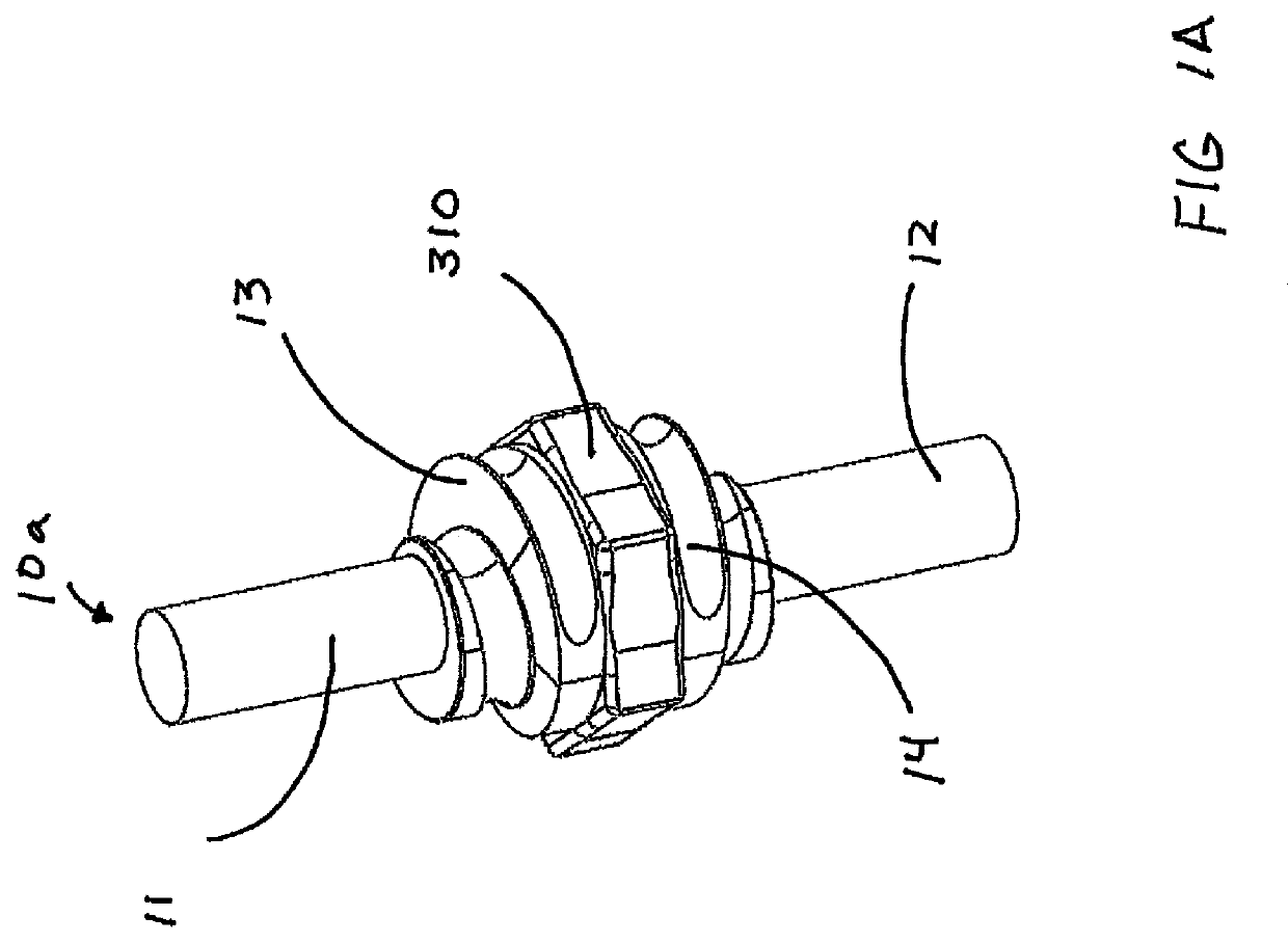
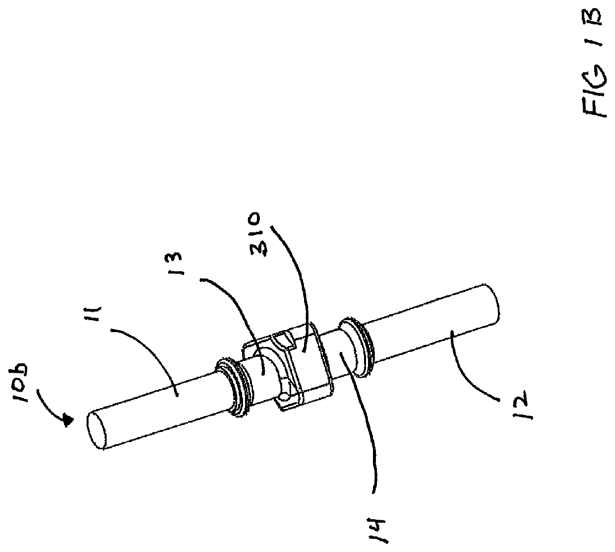
[0032]As shown in FIGS. 1, 1A, 1B, and 1C, 2C, and 2D the preferred embodiment of a projectile launching device has a first cam assembly 30 and a second cam assembly 40. More specifically as shown in FIGS. 1A, 1C, and 3A, a first pivoting shaft 10a is manufactured having a first end 11, a second end 12, and integrated cable tracks 13 and 14, the cable tracks 13 and 14 are mirror images of each other, and wherein the cables 110 and 120 are partially retained within the cable tracks 13 and 14. A pivoting shaft mating surface 310 is located between the first cable track 13 and the second cable track 14.

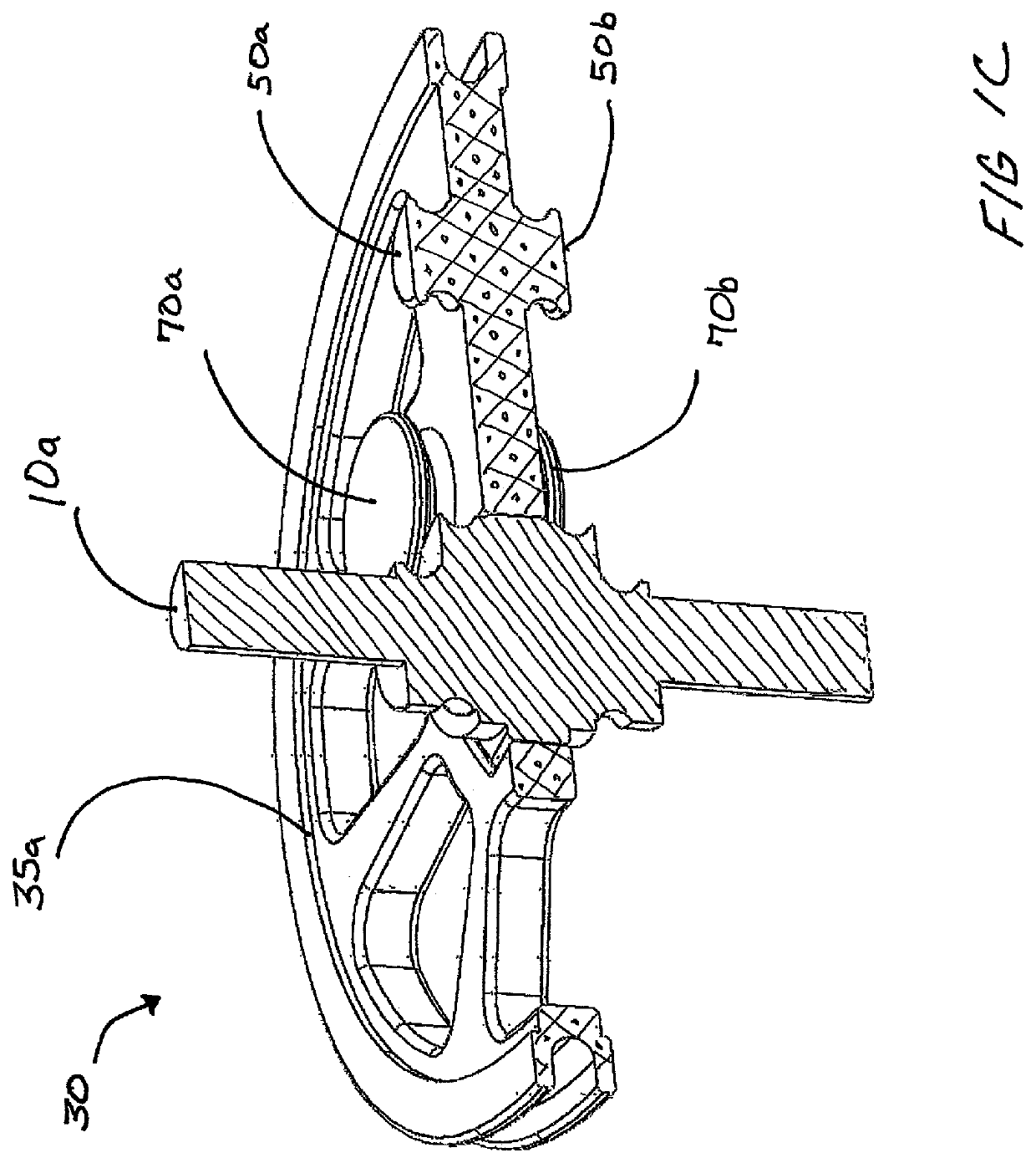
[0033]Specifically referring to FIG. 1C, a cutaway view illustrates the first cam assembly 30, the first pivoting shaft 10a is coupled with the first cam body 35a, wherein the first pivoting shaft 10a has a first cable track 13 on a first side of the cam body 35a and a second cable track 14 is on a second side of the cam body 35a. A first cable post 50a is provided on a first side of the...


PUM


Abstract

A projectile launching device includes self-timing without cam lean. The projectile launching device may include a frame, energy storing components, such as two limbs, two cam assemblies, a launch string, and at least one cable. The ends of the launch string are attached to the two cams. The cam assemblies are made having a cam body and a pivoting shaft with integrated cable track(s) coupled to each other. The two cam assemblies are built as mirror images of each other, or identical from side to side.

Description

CROSS-REFERENCE TO RELATED APPLICATIONS[0001]This a nonprovisional patent application, which claims the benefit of provisional patent application No. 62 / 845,931 filed on May 10, 2019.BACKGROUND OF THE INVENTIONField of the Invention[0002]The present invention relates generally to archery, and more specifically to the cam and axle configuration on an archery bow, which allows for the axle to be integrated with the cam, and turn in unison with the cam, as the cam rotates.Discussion of the Prior Art[0003]Generally, an archery cam pivots on an axle, the axle is constrained by limbs, whether by a hole through the limbs, supported on a pillow block, or some form of mounting bracket, wherein the axle is generally stationary. U.S. Pat. No. 7,938,109 to Larson discloses a synchronizing pulley assembly for a compound archery bow, wherein the axle may be integrated with the cam to allow a string track and first cable track rotate with the axle, but the second cable track is designed to pivot i...

Claims


Application Information

Patent Timeline
Patent Type & Authority Patents(United States)
IPC IPC(8): F41B5/10F41B5/12
CPCF41B5/105F41B5/123
Inventor KEMPF, JAMES J.ISENHOWER, REX E.
Owner ARCHERY INNOVATORS LLC
Learn More