Device for linearly moving a useful mass

a technology of useful mass and device, applied in the direction of hoisting equipment, gearing, manufacturing tools, etc., can solve the problems of loss of rigidity of the entire system, workpieces with low-quality surfaces, and inaccuracy of processing, so as to reduce the power requirement

Inactive Publication Date: 2008-09-09
SIEMENS AG
View PDF7 Cites 9 Cited by
  • Summary
  • Abstract
  • Description
  • Claims
  • Application Information

AI Technical Summary

Benefits of technology

[0008]According to an advantageous feature of the invention, the useful mass and the compensating mass can be moved in cooperation with a spindle that has two threads with an opposite lead, whereby the thread pitch for driving the compensating mass is smaller than the thread pitch for driving the useful mass. The travel of the compensating mass is thus kept small and the compensating mass can move at a relatively low speed, which advantageously reduces the power requirement.

Problems solved by technology

Dynamic movements along one axis can accidentally be transferred through the machine bed to another axis, which can result in processing inaccuracies, in particular workpieces that have low-quality surfaces.
In addition, when a rotary motion is transformed into a translational motion—either by a transformation through a ball roller spindle or alternatively a rack / pinion assembly—the forces generated by the linear element can result in a loss in stiffness of the entire system.
The transformation from a rotary motion into a translational motion is in general also associated with a significant loss in stiffness, which can be aggravated by the elasticity of the machine bed and / or the support of the drive train.
This limits the dynamic characteristic of the machine, unless substantial changes are made in the machine design.

Method used


Image

  • Device for linearly moving a useful mass
  • Device for linearly moving a useful mass
  • Device for linearly moving a useful mass

Examples


first embodiment

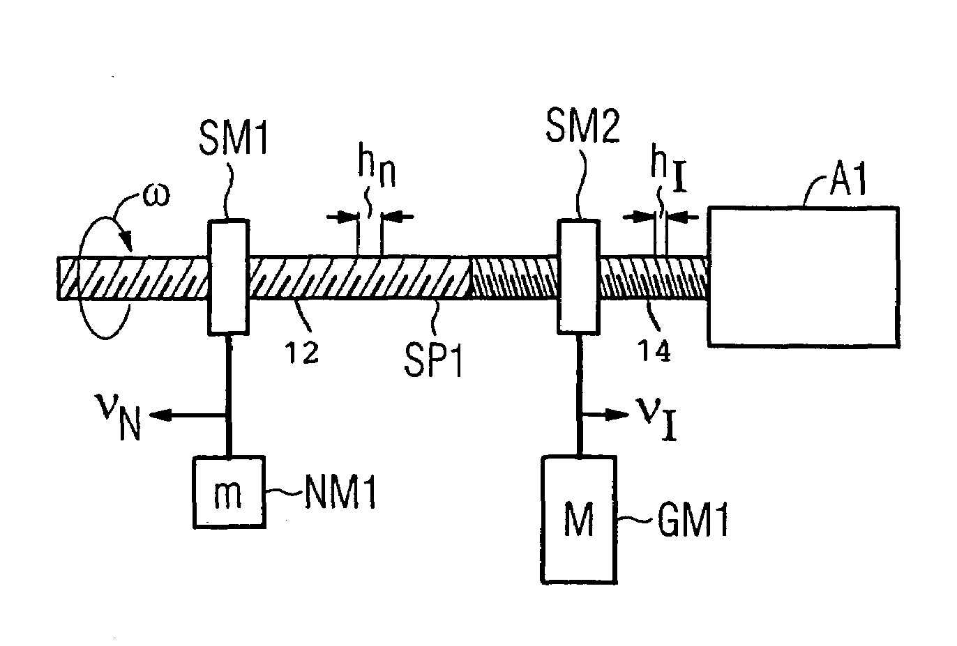
[0017]Turning now to the drawing, and in particular to FIG. 1, there is shown the invention with a single solid spindle SP1 coupled to a drive A1, in the present example a direct drive. The spindle SP1 can rotate, for example, with a speed ω in the rotation direction indicated by a curved arrow. The exemplary spindle SP1 has a left-handed threaded section 12 with a relatively high pitch hN and a right-handed threaded section 14 with a pitch hI that is comparatively smaller than the pitch hN. The threaded section 12 engages with a spindle nut SM1 that is connected with a useful mass NM1, as indicated by a heavy line. The useful mass NM1 has an exemplary physical mass m. In the right-handed threaded 14 of the spindle SP1 engages with a spindle nut SM2 that is mechanically connected with a compensating mass GM1 having an exemplary physical mass M. When the spindle SP1 rotates with the rotation speed ω, then the opposing lead of the spindle thread causes the spindle nuts SM1 and SM2 to ...

third embodiment

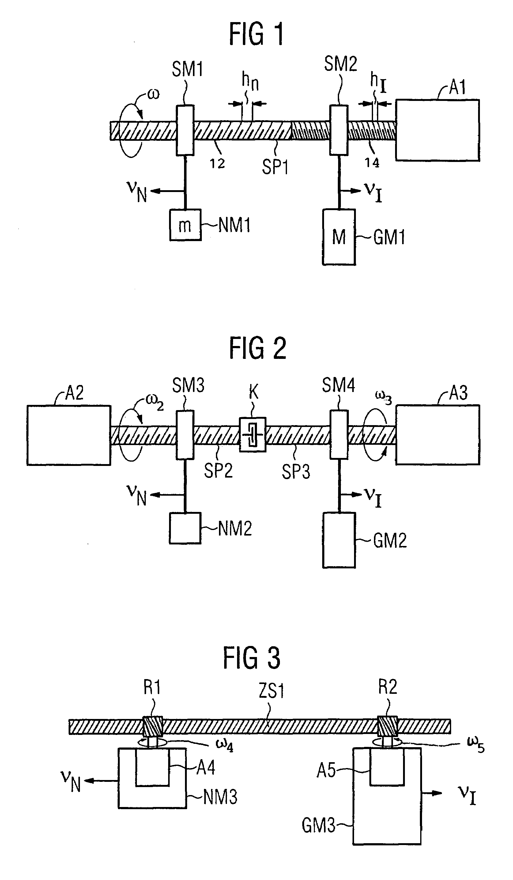
[0030]FIG. 3 shows the invention which employs a rack and pinion system instead of a spindle / spindle-nut system. This embodiment employs a stationary toothed rack ZS1 which engages with pinions R1 and R2. The exemplary useful mass NM3 is moved in a linear direction parallel to the rack ZS1 by a rotary drive A4 coupled to pinion R1 at a speed vN. The rotary drive A4 rotates with an angular rotation speed ω4, as indicated by a curved arrow. A compensating mass GM3 is moved on the rack ZS1 in the opposite direction of the useful mass NM3 by a rotary drive A5 coupled to pinion R2 at a speed vI. The rotary drive A5 rotates with an angular rotation speed ω5 in the opposite sense as the rotary drive A4. This arrangement eliminates or at least reduces undesired forces from being introduced by the toothed rack ZS into the machine. The equations for the physical motion listed above can be similarly applied to the rack / pinion configuration.

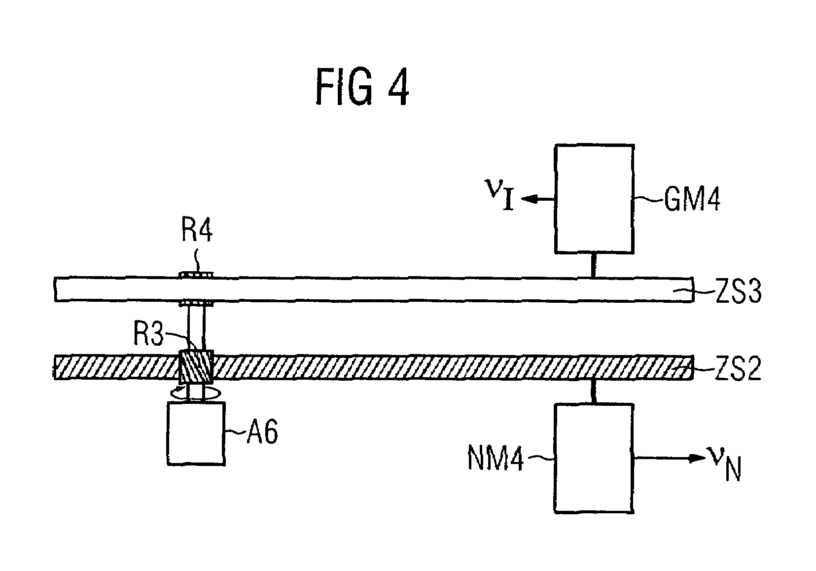
[0031]It will be understood that at least two racks ca...


PUM


Abstract

A device for linearly moving a useful mass is described. Typically, when a large useful mass is moved, relatively large forces are transferred by a spindle or a toothed rack to the corresponding machine or machine frame. These forces can be compensated by moving a compensating mass in the opposite direction of the useful mass.

Description

CROSS-REFERENCES TO RELATED APPLICATIONS[0001]This application claims the priority of German Patent Application, Serial No. 103 07 308.6, filed Feb. 20, 2003, pursuant to 35 U.S.C. 119(a)-(d), the disclosure of which is incorporated herein by reference.BACKGROUND OF THE INVENTION[0002]The present invention relates to a device for linearly moving a useful mass and by decoupling the momentum generated during the movement of the useful mass from the machine or machine foundation.[0003]Devices of this type have been used since many years with machine tools. It is also known that dynamic processes used to accelerate useful masses along linear axes produce significant forces that have to be transferred to or absorbed by the machine bed or machine foundation. Dynamic movements along one axis can accidentally be transferred through the machine bed to another axis, which can result in processing inaccuracies, in particular workpieces that have low-quality surfaces. In addition, when a rotary...

Claims


Application Information

Patent Timeline
Patent Type & Authority Patents(United States)
IPC IPC(8): F16H1/14B23Q5/40B23Q11/00F16F7/10F16F15/28F16H25/20H02K7/06
CPCB23Q5/40F16F7/10F16F15/28F16H25/20H02K7/06F16F2232/04Y10T74/19828Y10T74/19726Y10T74/1967Y10T74/19698Y10T74/19837Y10T74/18576Y10T74/19702
Inventor HAMANN, JENSSCHAFERS, ELMARWEDEL, BERND
Owner SIEMENS AG
Why Eureka
Try Eureka