Rail inspection system

a rail inspection and rail technology, applied in the direction of railway signalling and safety, railway profile gauges, instruments, etc., can solve the problem of difficulty in and achieve the effect of accurately detecting the defect of the rail

Active Publication Date: 2021-04-27
HITACHI HIGH TECH SOLUTIONS CORP
View PDF22 Cites 10 Cited by
  • Summary
  • Abstract
  • Description
  • Claims
  • Application Information

AI Technical Summary

Benefits of technology

[0007]According to the invention, the defect of the railroad rail can be detected accurately.

Problems solved by technology

Thus, an error generated by a vibration of a measuring vehicle (a railroad vehicle for inspecting a state of a track or an overhead line) becomes large, and it is difficult to accurately detect the defect of the railroad rail.

Method used


Image

  • Rail inspection system
  • Rail inspection system
  • Rail inspection system

Examples


first embodiment

Effect of First Embodiment

[0081]As described above, in the present embodiment, the detection part group (34) is provided which has a plurality of detection parts (34-1 to 34-N) which detect the first inspection signal (X) corresponding to the first phase (0°) of the output signal and the second inspection signal (Y) corresponding to the second phase (90°) of the output signal with respect to the output signal output from each of the receiver coils when the sensor part group (21) moves in the laying direction of the railroad rail (100). Thus, the defect of the railroad rail can be detected accurately.

[0082]In the present embodiment, the output processing part (44) is further provided which outputs the intensity distributions of the displaying target signals (X, Y, R, θ) corresponding to the plurality of sensor parts (21-1 to 21-N) as the two-dimensional image (130) when the first inspection signal (X) and the second inspection signal (Y) or the result (R, θ) obtained by performing th...

second embodiment

Effect of Second Embodiment

[0123]As described above, the present embodiment further includes the plurality of correction signal generating parts (50-1 to 50-N) which output the correction signals which have the same frequency as that of the oscillation signal and the amplitude and the phase different from those of the oscillation signal to the plurality of respective corresponding receiver coils (6-1 to 6-N), and the subtraction parts (52-1 to 52-N) which subtract the corresponding correction signals from the output signals of the plurality of sensor parts (21-1 to 21-N) respectively and supply respective subtraction results to the corresponding detection parts (34-1 to 34-N).

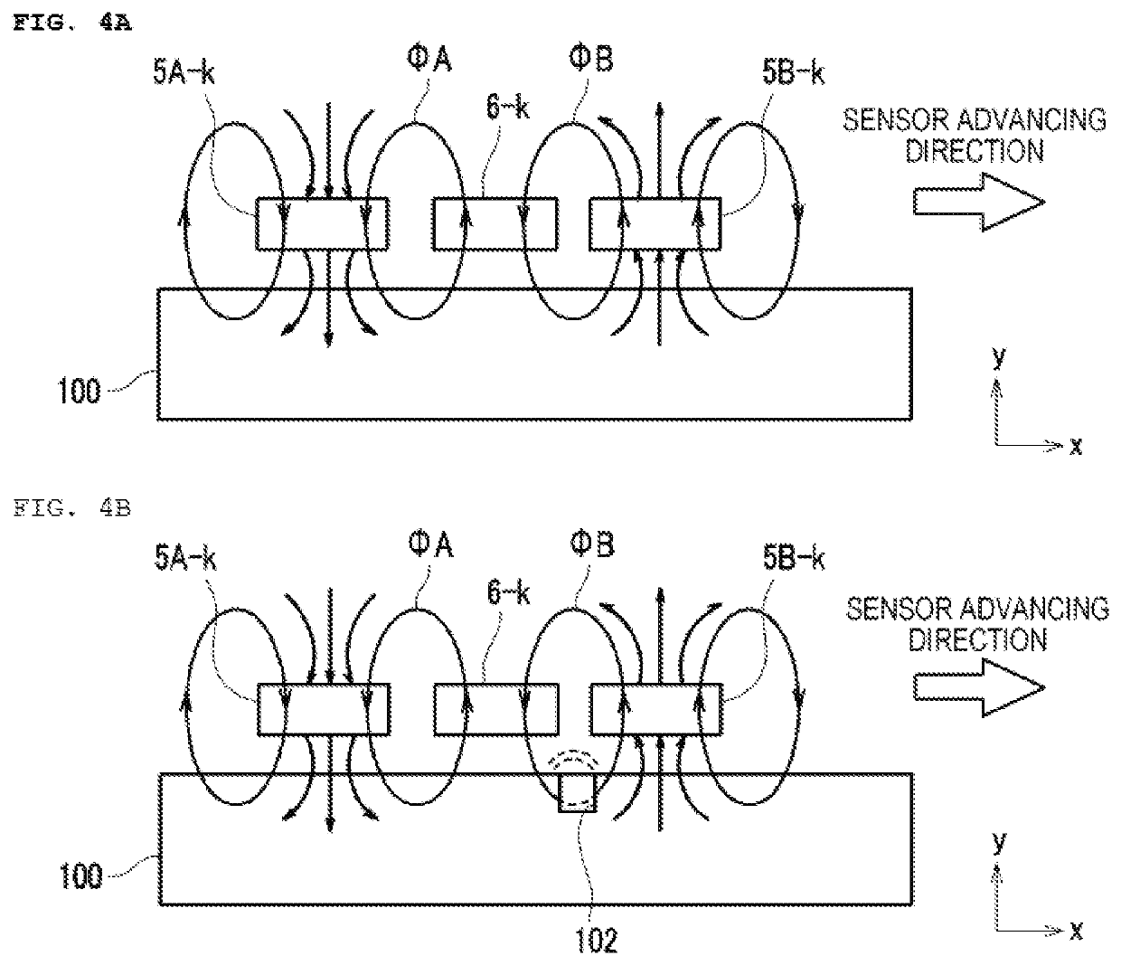
[0124]Accordingly, even in a case where the processing accuracy of the oscillator coils 5A-k and 5B-k (see FIG. 4) is low, the noise signal can be cancelled electrically, and the defect of the railroad rail 100 can be detected precisely.

third embodiment

[0125]Next, a third embodiment of the invention will be described. Incidentally, in the following description, in some cases, the parts corresponding to respective parts in FIGS. 1 to 13 are denoted by the same reference signs, and the description thereof is not given.

[0126]FIG. 14 is a block diagram illustrating the overall configuration of a rail inspection system 1b according to the third embodiment of the invention. The appearance configuration of the rail inspection system 1b of the present embodiment is similar to that of the first embodiment (see FIGS. 1 to 3). In addition, the configuration of the detector 2 is similar to that of the first embodiment (see FIG. 5). However, instead of the processor 3 (see FIG. 5) of the first embodiment, a processor 3b is applied in the present embodiment. Incidentally, in FIG. 14, the inner portion of the evaluation device 4 is not illustrated, but the configuration of the evaluation device 4 is also similar to that of FIG. 5.

[0127]Similarly...


PUM

PropertyMeasurementUnit
oscillation frequencyaaaaaaaaaa
frequencyaaaaaaaaaa
frequencyaaaaaaaaaa

Abstract

Provided is a rail inspection system capable of accurately detecting a defect of a railroad rail. The system includes: a sensor part group that has a plurality of sensor parts having receiver coils, and first oscillator coils and second oscillator coils corresponding to the receiver coils being arranged in a line parallel in a width direction of a railroad rail to be inspected; an oscillation part that supplies an oscillation signal to each of the first oscillator coils and the second oscillator coils; and a detection part group that has a plurality of detection parts to detect, with respect to an output signal from each of the receiver coils when the sensor part group moves in a laying direction of the railroad rail, a first inspection signal corresponding to a first phase of the output signal and a second inspection signal corresponding to a second phase of the output signal.

Description

TECHNICAL FIELD[0001]The present invention relates to a rail inspection system.BACKGROUND OF THE INVENTION[0002]As a background art in this technical field, there is disclosed in Patent Document 1. A defect such as a crack may occur in a rail used for a railroad or the like. When such a kind of defect is left, a problem such as a breakage of the rail occurs. Thus, preferably, a nondestructive inspection is performed regularly on the rail. For example, the abstract of the following PTL 1 describes that “according to one embodiment, the present technique provides a testing apparatus for testing material integrity in an object. The testing apparatus includes an electrical conductor and a sensing device. In the exemplary testing device, the electrical conductor extends in a generally linear direction and is configured to route current in a direction generally transverse to a longitudinal axis of the object being tested. Routing of current through the electrical conductor creates remote ...

Claims


Application Information

Patent Timeline
Patent Type & Authority Patents(United States)
IPC IPC(8): G01N27/82G01N27/83B61K9/10B61L23/04
CPCG01N27/83B61K9/10B61L23/044G01N27/82G01N2291/2623G01N27/87
Inventor KAWABATA, RYUZOSUZUKI, HIROSHIYAMAMOTO, KENJIKANDORI, AKIHIKO
Owner HITACHI HIGH TECH SOLUTIONS CORP
Why Eureka
Try Eureka