
Method and device for localizing an insulation fault in an operating electrical equipment connected to a power supply system

a technology of electrical equipment and faults, applied in short-circuit testing, impedence measurement, instruments, etc., can solve problems such as time- and cost-intensive fault localization, insidious threat in particular to people, and reduce the insulation resistance value, so as to achieve less time- and cost-intensive effects

Active Publication Date: 2021-04-27
BENDER SA
View PDF13 Cites 0 Cited by
  • Summary
  • Abstract
  • Description
  • Claims
  • Application Information

AI Technical Summary

Benefits of technology

The present invention proposes a method and device for quickly locating faults in electrical equipment connected to a power supply system. This method is faster and less expensive than current methods, and it allows for the equipment to be operated while being monitored for faults. By analyzing the timing of the fault and the equipment being turned on, the method can narrow down the location of the fault more quickly, resulting in faster and more efficient maintenance of equipment.

Problems solved by technology

In a grounded power supply system, an insulation fault can manifest itself as a residual current which does not trigger a fault-current protective device but in the long term poses an insidious threat in particular to people who come into contact with electrically conductive installation parts.
In ungrounded power supply systems, a decreasing insulation resistance value can pose a risk to operational safety.
As a rule, the fault localization is a time- and cost-intensive task since the fault must be eliminated as quickly as possible but the fault location is as of yet unknown.
With a sufficient amount of measuring current transformers, a selectivity all the way to individual sockets can be attained which, however, disadvantageously encompasses a corresponding material and installation expenditure.
The fault localization is therefore often very cumbersome in particular in faults which occur in connected operating electrical equipment, such as consumers or generators.

Method used


Image

  • Method and device for localizing an insulation fault in an operating electrical equipment connected to a power supply system
  • Method and device for localizing an insulation fault in an operating electrical equipment connected to a power supply system

Examples


Embodiment Construction

[0048]The advantageous features of the embodiments are explained in the following description and in the drawings, which explain in an exemplary manner a preferred embodiment of the device and method according to the invention.

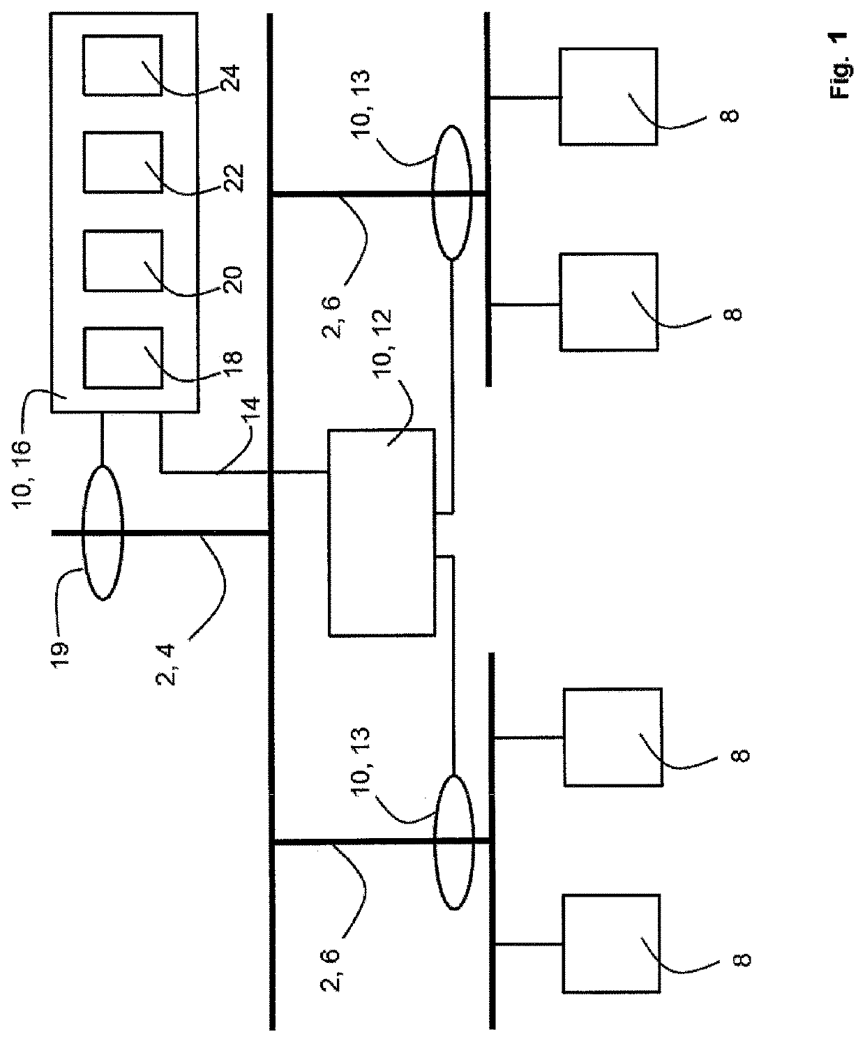
[0049]FIG. 1 illustrates in a schematic view a device according to the invention for localizing an insulation fault in an operating electrical equipment connected to a power supply system; and

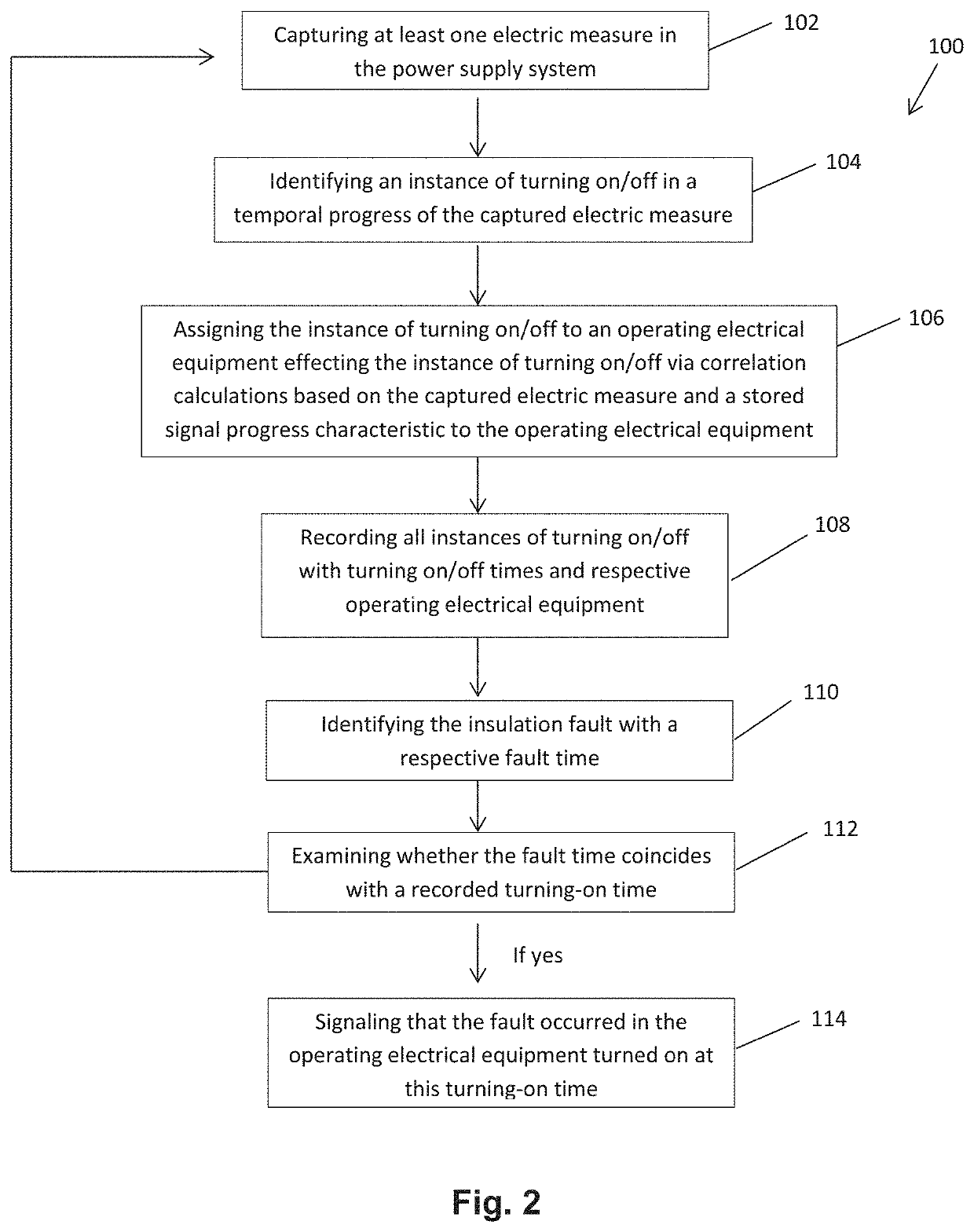
[0050]FIG. 2 illustrates a method according to the invention for localizing an insulation fault in an operating electrical equipment connected to a power supply.

[0051]Illustrated is a branched power supply system 2 which consists of a main system 4 and two subsystems 6. Consumers or generators are connected to the subsystems 6 as electric operating electrical equipment 8.

[0052]The device 10 according to the invention for localizing the insulation fault is illustrated in a functional block diagram and comprises an electric monitoring device 12, which is connected to an ide...


PUM


Abstract

The invention relates to a method and a device (10) for localizing an insulation fault in an operating electrical equipment (8) connected to a power supply system (2). Fundamental function blocks of the invention are an electric monitoring device (12), which identifies an insulation fault and communicates a respective fault time to an identifying device (16) via a communication channel (14), said identifying device (16) identifying a faulty operating electrical equipment (8) by electrical equipment of a turning-on / -off signal progress characteristic to the particular operating electrical equipment (8).

Description

BACKGROUND OF THE INVENTION[0001]The invention relates to a method and a device for localizing an insulation fault in an operating electrical equipment connected to a power supply system.[0002]The foundation for safely supplying electrical energy is based on reliable power supply systems. The high availability of power supply demands highly complex electric installations which are provided with protective and monitoring devices in order to identify faults on time and to be able to implement a time- and cost-saving fault localization.[0003]In a grounded power supply system, an insulation fault can manifest itself as a residual current which does not trigger a fault-current protective device but in the long term poses an insidious threat in particular to people who come into contact with electrically conductive installation parts. In ungrounded power supply systems, a decreasing insulation resistance value can pose a risk to operational safety. It is thus necessary to duly identify, l...

Claims


Application Information

Patent Timeline
IPC IPC(8): G01R31/08G01R27/18G01R31/50
CPCG01R31/50G01R31/08G01R31/52
Inventor PIELER, DIRKWAGNER, JOACHIM
Owner BENDER SA
Learn More