
Motion sensing wi-fi sensor networks for continuous 3D modeling and prediction of facility responses to disturbances

a technology of motion sensing wi-fi and sensor networks, applied in the field of continuous 3d modeling and prediction of facility responses to disturbances, can solve the problems of relatively intensive structural inspection methods, and achieve the effects of improving reliability, reducing labor intensity, and increasing the number of years of battery operation

Active Publication Date: 2021-05-04
MASSACHUSETTS INST OF TECH +1
View PDF5 Cites 0 Cited by
  • Summary
  • Abstract
  • Description
  • Claims
  • Application Information

AI Technical Summary

Benefits of technology

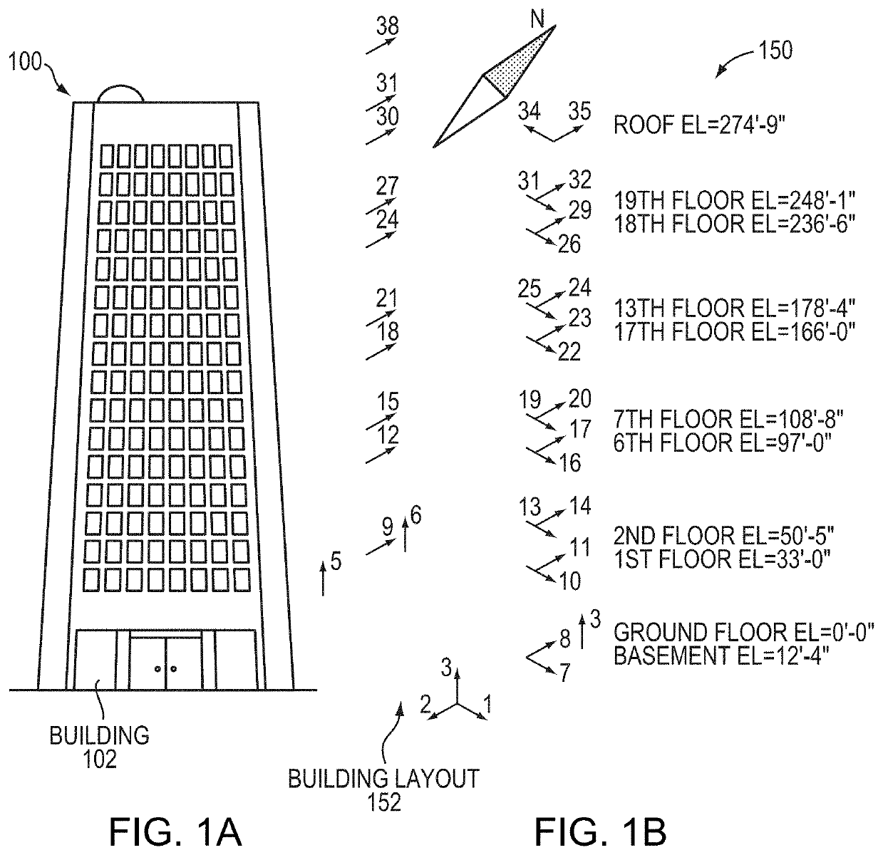
[0007]The system and method employ machine learning techniques to build a predictive 3D model of the responses of the various parts of the structure to continuous real 3D stresses. A dense grid of sensors further provides redundancy and a variety of collected data, aids noise suppression and provides a large data base for the machine learning techniques. This approach can provide more accurate information on facility integrity aspects than current technologies can provide. As such, this information can check the structural integrity and identifying problems in a timely fashion or in real-time. In fact, data bases of real 3D responses measured through continuous monitoring can be used to build accurate 3D models. The 3D models can then be used to predict, for example, catastrophic failures under extreme or long term loading conditions.
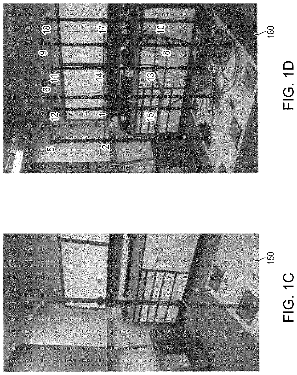
[0008]In an embodiment of the present invention, a damage detection process can be employed with a wireless sensor network for sensing damage and disturbances in various structures. The wireless sensor network hardware may be made smaller, ruggedized for outdoor use, rechargeable, and low power to enable multiyear battery operation.
[0014]3D visualization can facilitate analysis of collected and inferred data. Based on 3D models of the structure, a system and method can provide a visualization of a unified environment having raw and processed data, and results of the various computational models. Visualizations can include standard color-coded approaches and re-rendering the motion with different types of magnification applied. Methods for real-time 3D pattern analysis of the sensor data can be employed, such as grouping patterns in the data, eliminating noise, clustering, and magnifying selective components of the motion such as rotations or translation.
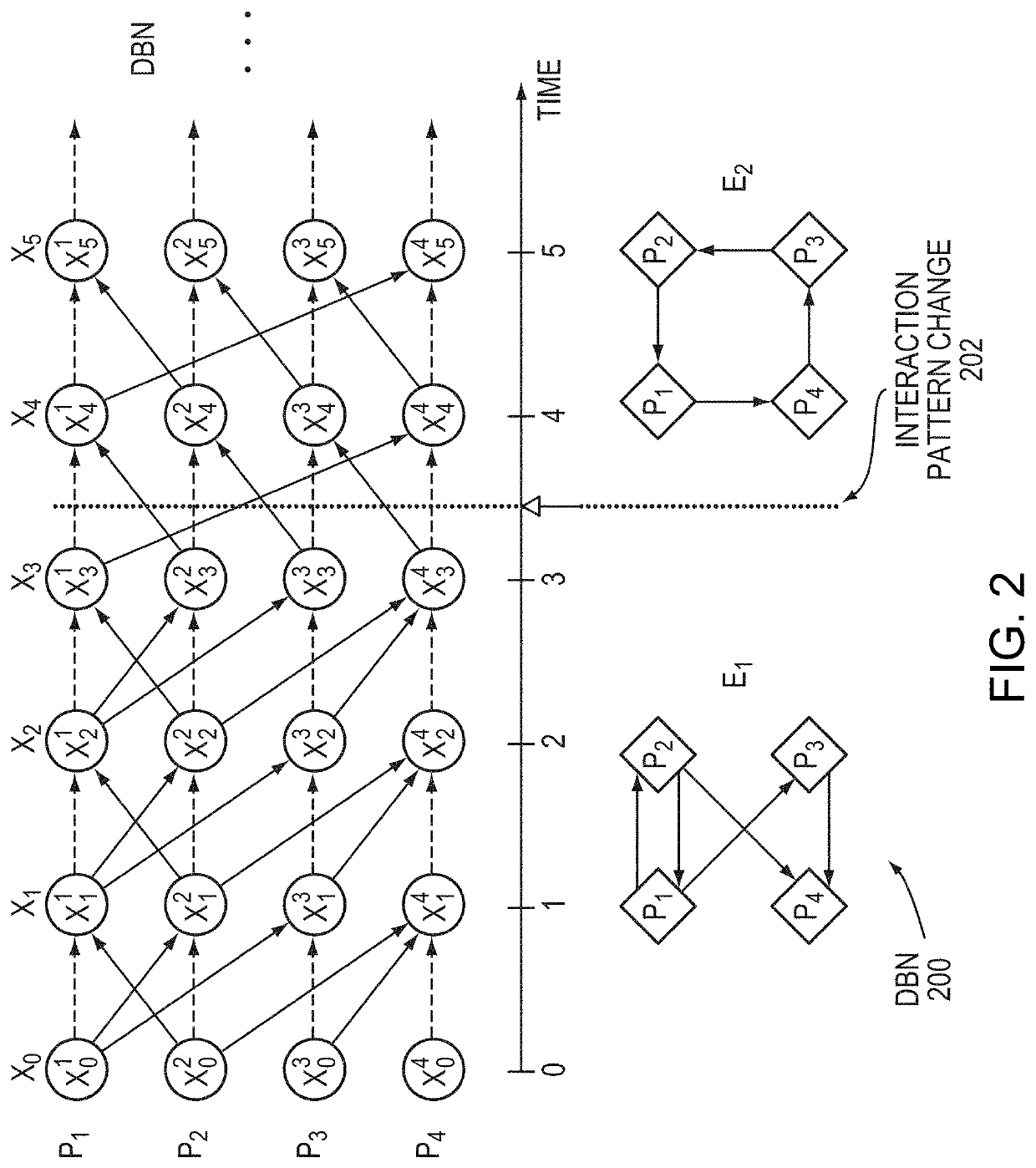
[0037]A non-transitory computer-readable medium configured to store instructions for structural health monitoring (SHM), the instructions, when loaded and executed by a processor, causes the processor to, sense vibrations at a plurality of locations of a structure by a plurality of time-synchronized sensors. The instructions further cause the processor to determine a first set of dependencies of all sensors of the time-synchronized sensors at a first sample time to any sensors of a second sample time. The instructions further cause the processor to determine a second set of dependencies of all sensors of the time-synchronized sensors at the second sample time to any sensors of a third sample time. The second sample time is later than the first sample time, and the third sample time being later than the second sample time. The instructions further cause the processor to determine whether the structure has changed if the first set of dependencies is different from the second set of dependencies.

Problems solved by technology

These structural inspection methods are relatively intensive because they depend on the experience of the inspector and the time to inspect suspected damaged locations in the structure.

Method used


Image

  • Motion sensing wi-fi sensor networks for continuous 3D modeling and prediction of facility responses to disturbances
  • Motion sensing wi-fi sensor networks for continuous 3D modeling and prediction of facility responses to disturbances
  • Motion sensing wi-fi sensor networks for continuous 3D modeling and prediction of facility responses to disturbances

Examples


Embodiment Construction

[0061]A description of example embodiments of the invention follows.

[0062]Adding additional sensors to the structure, such that an indication of where potential locations of damage to the structure can be closely inspected, can be advantageous. These potential locations of damage can be useful for reduces the time and effort necessary for structural inspection.

[0063]Structural health monitoring (SHM) instruments a structure with sensors to collect data and derives some information from the collected data to determine whether the structure has changed. A detected change in the structure can then be attributed to damage that can be more closely investigated. In general, collected data is processed into features that may indicate these changes in the structure, and, in some cases, statistical or probabilistic discrimination of these features can separate data collected from intact and changed structures.

[0064]Statistical methods can discriminate feature changes as a result of structura...


PUM


Abstract

Structural health monitoring (SHM) is essential but can be expensive to perform. In an embodiment, a method includes sensing vibrations at a plurality of locations of a structure by a plurality of time-synchronized sensors. The method further includes determining a first set of dependencies of all sensors of the time-synchronized sensors at a first sample time to any sensors of a second sample time, and determining a second set of dependencies of all sensors of the time-synchronized sensors at the second sample time to any sensors of a third sample time. The second sample time is later than the first sample time, and the third sample time is later than the second sample time. The method then determines whether the structure has changed if the first set of dependencies is different from the second set of dependencies. Therefore, automated SHM can ensure safety at a lower cost to building owners.

Description

COMMON OWNERSHIP UNDER JOINT RESEARCH AGREEMENT 35 U.S.C. 102(C)[0001]The subject matter disclosed in this application was developed, and the claimed invention was made by, or on behalf of, one or more parties to a joint Research Agreement that was in effect on or before the effective filing date of the claimed invention. The parties to the Joint Research Agreement are as follows Shell International Exploration & Production.BACKGROUND[0002]Structural inspection ensures the integrity of structures. Structural inspection includes informal subjective methods such as visual or hammer testing, and quantitative modern methods such as ultrasound, x-ray, and radar non-destructive testing techniques. These structural inspection methods are relatively intensive because they depend on the experience of the inspector and the time to inspect suspected damaged locations in the structure. Inspections are typically carried out periodically.SUMMARY OF THE INVENTION[0003]An embodiment of the present ...

Claims


Application Information

Patent Timeline
Patent Type & Authority Patents(United States)
IPC IPC(8): G06F30/23G01M5/00G01H1/00H04N7/18G06N20/00
CPCG06F30/23G01H1/00G01M5/0033G01M5/0066G06N20/00H04N7/181
Inventor FREEMAN, WILLIAM T.BUYUKOZTURK, ORALFISHER, III, JOHN W.DURAND, FREDERICMOBAHI, HOSSEINWADHWA, NEALDZUNIC, ZORANCHEN, JUSTIN G.LONG, JAMESMOHAMMADI GHAZI, REZASMIT, THEODERICUS JOHANNES HENRICUSKAPUSTA, SERGIO DANIEL
Owner MASSACHUSETTS INST OF TECH
Learn More