Supercharge Your Innovation With Domain-Expert AI Agents!

Imaging device and control method therefor

a technology of a camera and an image sensor, which is applied in the field of imaging devices, can solve the problems of underexposure or pixel saturation, and the inability to perform accurate photometry in one-time exposur

Active Publication Date: 2021-05-04
CANON KK
View PDF2 Cites 1 Cited by
  • Summary
  • Abstract
  • Description
  • Claims
  • Application Information

AI Technical Summary

Benefits of technology

The present invention is related to an imaging device that can capture images using a light sensor. The device includes a capacitance varying unit, an amplification unit, and a control unit. The control unit controls the light emission unit, the capacitance varying unit, and the amplification unit. The control unit decides the gains for amplification based on the electrostatic capacitance of the sensor and the gain set in the amplification unit. The control unit also controls the display or recording of the image signal based on the gains. The technical effect of this invention is to improve the quality and efficiency of imaging devices by optimizing the amplification process based on the electrostatic capacitance of the sensor.

Problems solved by technology

Therefore, when an exposure result at the time of the preliminary light emission is not within a dynamic range of the linear system sensor, a so-called underexposure or pixel saturation may occur, and thus accurate photometry may not be performed in one-time exposure.

Method used


Image

  • Imaging device and control method therefor
  • Imaging device and control method therefor
  • Imaging device and control method therefor

Examples


first embodiment

[0023]FIG. 1 is a diagram illustrating an overall configuration of an imaging device 100 according to an embodiment of the invention. Hereinafter, a subject side is defined as a front side. Positional relations between units will be described. A first lens group 101 is a lens group disposed on the front side of an imaging optical system and is held to advance and retreat in an optical axis direction in a lens barrel. A diaphragm 102 is an optical member that performs light quantity adjustment at the time of photographing by adjusting an opening diameter and is located between the first lens group 101 and a second lens group 103. The second lens group 103 is integrated with the diaphragm 102 to advance and retreat in the optical axis direction. The second lens group 103 is a lens group that has a magnification changing action (zoom function) in cooperation with an advancing or retreating operation of the first lens group 101. A third lens group 104 is a lens group that performs focus...

second embodiment

[0087]Next, a second embodiment of the invention will be described. In the first embodiment, the case in which the FD gain is raised at the time of acquisition of the modulated light image data has been described. In the embodiment, however, a case in which the FD gain is reduced at the time of acquisition of the modulated light image data will be described with reference to FIG. 14. Differences from the first embodiment will be described and similar factors to those of the first embodiment will be omitted. For omission of the description, the same applies to embodiments to be described below.

[0088]FIG. 14 is a timing chart illustrating a reading operation of the image sensor 107 at the time of acquisition of modulated light image data 1 and modulated light image data 2. Only the signal fdinc_i which is a difference between FIGS. 11C and 13C will be described.

[0089]In the embodiment, in a case of either low ISO sensitivity setting or high ISO sensitivity, the level of the signal fdi...

third embodiment

[0091]Next, a third embodiment of the invention will be described. In the first and second embodiments, the case in which the FD gain is fixed at the time of acquisition of the modulated light image data has been described. In the embodiment, a case in which the FD gain is set to be variable at the time of acquisition of the modulated light image data will be described with reference to FIG. 15. A horizontal synchronization signal (referred to as an HD) is added to the timing chart of FIG. 15. In reading of an i-th row indicated by the horizontal synchronization signal HD, signal reading at a gain equivalent to ISO100 is performed. In subsequent reading of an i+1-th row, signal reading at a gain equivalent to ISO1600 is performed.

[0092]When the pixel signals of the i-th row are read at the gain equivalent to ISO100, the CPU 109 first asserts the horizontal synchronization signal HD corresponding to a reading period equivalent to one row. Subsequently, the CPU 109 sets the level of t...


PUM


Abstract

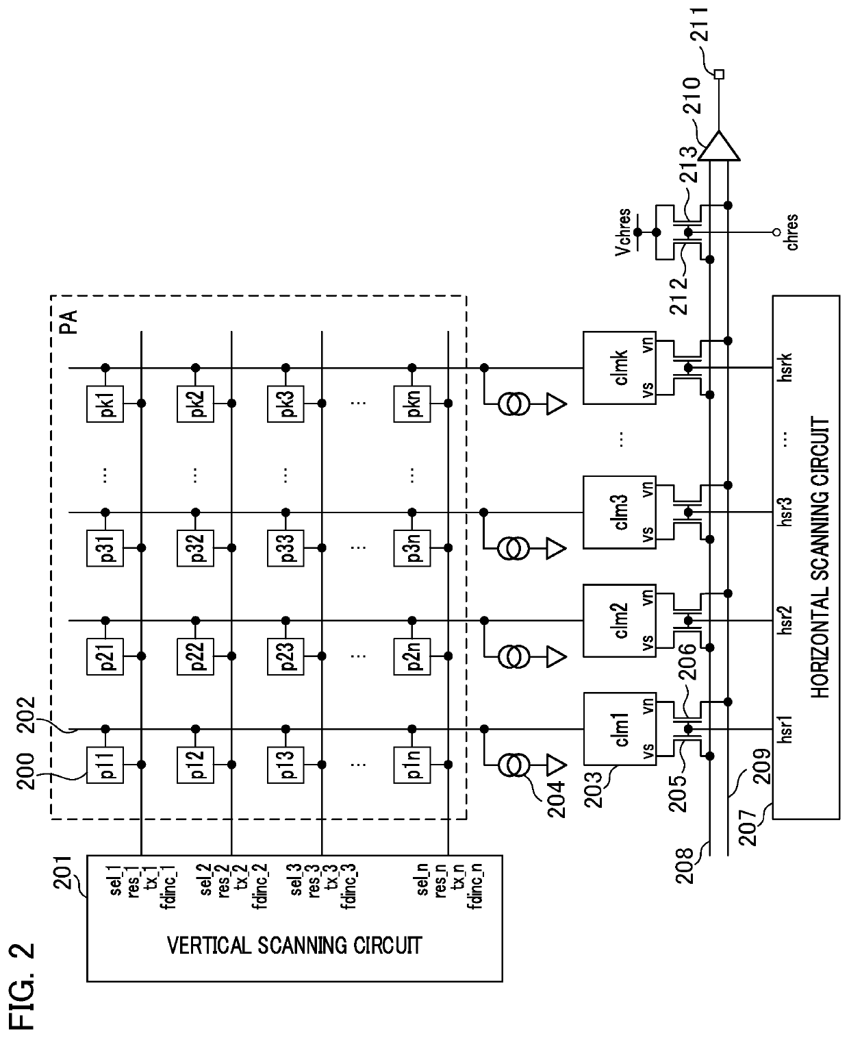
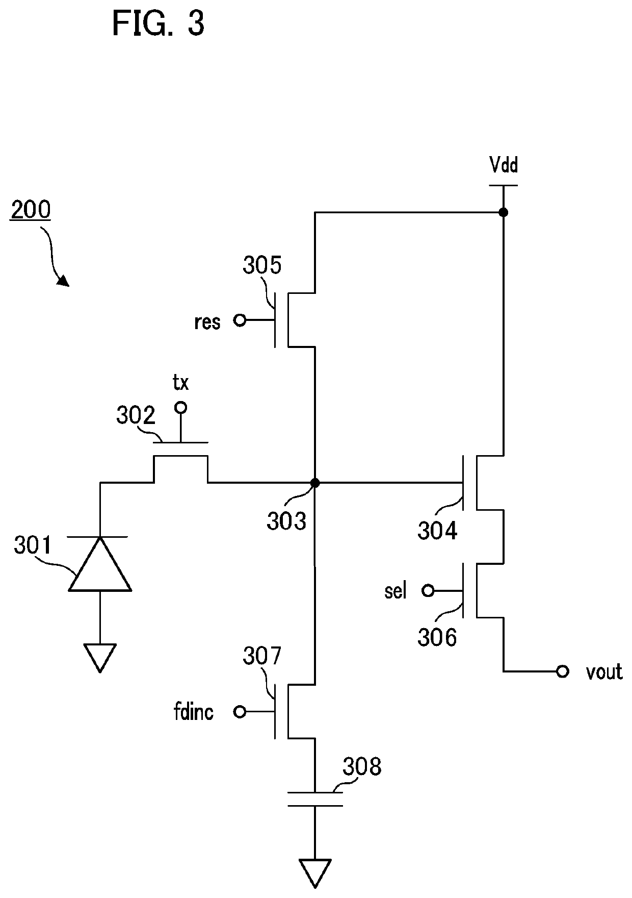
An imaging device controls a light emission unit to perform pre-light emission and decides an amount of light emitted in imaging. In a plurality of pixel units included in an image sensor, a switch that connects or does not connect an additional capacitor to a floating diffusion (FD) unit is provided. An amplification unit for a pixel signal can set a plurality of gains. A CPU controls the switch such that the FD unit is connected to the additional capacitor or the FD unit is not connected to the additional capacitor in accordance with an imaging condition. When image data for light modulation is acquired or when image data used for live-view display or recording is acquired, the CPU performs control such that the switch and the amplification unit amplify the pixel signal in different gain settings.

Description

BACKGROUND OF THE INVENTIONField of the Invention[0001]The present invention relates to an imaging device and a control method therefor capable of ensuring a dynamic range in accordance with an imaging condition.Description of the Related Art[0002]As photometric schemes of controlling exposure control of imaging devices, there are a first scheme of performing photometry using a compression system sensor for photometry and a second scheme of performing photometry using a linear system sensor on an imaging surface. The second scheme has a narrower dynamic range (hereinafter also referred to as a DR) in which photometry is possible than the first scheme, and therefore accurate photometry may not be performed on a subject with a large contrast. In particular, when stroboscopic light modulation for calculating an amount of emitted light at the time of photographing is performed in stroboscopic photographing by performing preliminary light emission and performing photometry of light refle...

Claims


Application Information

Patent Timeline
Patent Type & Authority Patents(United States)
IPC IPC(8): H04N5/235H04N5/243H04N5/3745H04N5/378H04N23/76
CPCH04N5/2352H04N5/2354H04N5/2355H04N5/243H04N5/378H04N5/37452H04N23/72H04N25/40H04N23/74H04N25/771H04N25/78H04N25/532H04N23/76H04N23/741H04N25/75
Inventor MAETA, SHINICHI
Owner CANON KK
Features
  • R&D
  • Intellectual Property
  • Life Sciences
  • Materials
  • Tech Scout
  • Unparalleled Data Quality
  • Higher Quality Content
  • 60% Fewer Hallucinations
Learn More