Supercharge Your Innovation With Domain-Expert AI Agents!

Method, system and apparatus for obstacle handling in navigational path generation

a technology of navigational path and obstacle handling, applied in image enhancement, scene recognition, instruments, etc., can solve the problems of reducing system efficiency, increasing computational load, complex and fluid environment in which objects are managed,

Active Publication Date: 2021-05-11
ZEBRA TECH CORP
View PDF441 Cites 7 Cited by
  • Summary
  • Abstract
  • Description
  • Claims
  • Application Information

AI Technical Summary

Benefits of technology

The patent describes a method and apparatus for planning a navigational path for a mobile automation apparatus in a complex environment. The method involves obtaining localization of the mobile apparatus and a map of the environment, detecting obstacles, and generating a dynamic perimeter region around the obstacles to identify areas where the mobile apparatus may encounter obstacles. The system then generates a navigational path that avoids the obstacles and ensures efficient system operation. The technical effect of this invention is to improve the efficiency and accuracy of obstacle detection and path planning for mobile automation systems in complex environments.

Problems solved by technology

Environments in which objects are managed, such as retail facilities, may be complex and fluid.
Errors in localization of the mobile automation apparatus in the environment impose an increased computational load and reduce system efficiency
The path generation mechanisms implemented by the path generator 254, however, typically require the path generator 254 to distinguish between space in the environment that is obstructed, and therefore unsuitable for traversal by a navigational path, and space that is unobstructed, and therefore suitable for traversal by a navigational path.

Method used


Image

  • Method, system and apparatus for obstacle handling in navigational path generation
  • Method, system and apparatus for obstacle handling in navigational path generation
  • Method, system and apparatus for obstacle handling in navigational path generation

Examples


Embodiment Construction

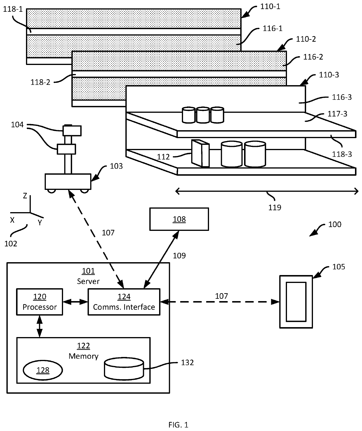
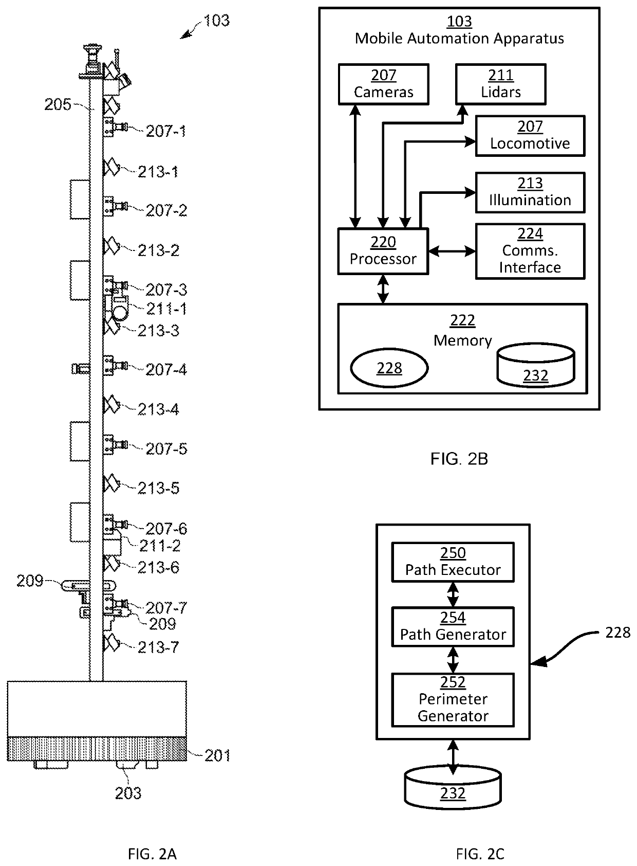
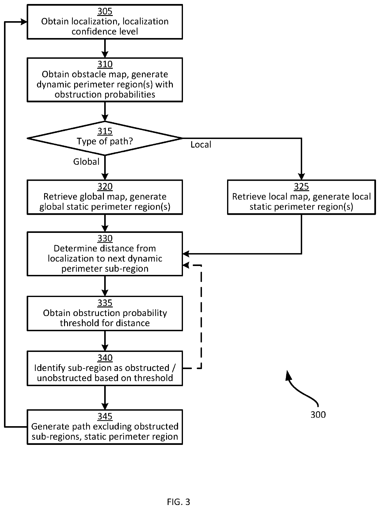
[0019]Examples disclosed herein are directed to a method of navigational path planning for a mobile automation apparatus, the method comprising: obtaining (i) a localization of the mobile automation apparatus in a common frame of reference and (ii) a localization confidence level of the mobile automation apparatus; detecting an obstacle boundary by one or more sensors disposed on the mobile automation apparatus; obtaining an obstacle map indicating the detected obstacle boundary in the common frame of reference; generating a dynamic perimeter region of the detected obstacle boundary, the dynamic perimeter region defining, for a set of distances from the detected obstacle boundary, respective obstruction probabilities according to the localization confidence level; obtaining a predefined environmental map indicating, in the common frame of reference, a predefined obstacle boundary; generating, for the predefined obstacle boundary, a static perimeter region defining obstructed space; ...


PUM


Abstract

A method of navigational path planning for a mobile automation apparatus includes: obtaining an apparatus localization in a common frame of reference and a localization confidence level; detecting an obstacle boundary by one or more apparatus sensors; obtaining an obstacle map indicating the obstacle boundary in the frame of reference; generating a dynamic perimeter region of the obstacle boundary defining obstruction probabilities for respective distances from the obstacle boundary according to the localization confidence level; obtaining an environmental map indicating a predefined obstacle boundary; generating, for the predefined obstacle boundary, a static perimeter region defining obstructed space; identifying an obstructed portion of the dynamic perimeter region based on the obstruction probabilities and the apparatus localization; generating a navigational path traversing unobstructed space, that excludes the obstructed portion of the dynamic perimeter region, and the static perimeter region; and controlling the apparatus to traverse the generated navigational path.

Description

BACKGROUND[0001]Environments in which objects are managed, such as retail facilities, may be complex and fluid. For example, a retail facility may include objects such as products for purchase, a distribution environment may include objects such as parcels or pallets, a manufacturing environment may include objects such as components or assemblies, a healthcare environment may include objects such as medications or medical devices.[0002]A mobile automation apparatus may be employed to perform tasks within the environment, such as capturing data for use in identifying products that are out of stock, incorrectly located, and the like. To travel within the environment, a path is generated. Errors in localization of the mobile automation apparatus in the environment impose an increased computational load and reduce system efficiencyBRIEF DESCRIPTION OF THE SEVERAL VIEWS OF THE DRAWINGS[0003]The accompanying figures, where like reference numerals refer to identical or functionally simila...

Claims


Application Information

Patent Timeline
Patent Type & Authority Patents(United States)
IPC IPC(8): G05D1/02G05D1/00G06K9/00G06T7/62G06T7/70
CPCG05D1/0214G05D1/0088G05D1/0238G05D1/0274G06K9/00805G06T7/62G06T7/70G05D2201/0216G06T2207/30261G06T2207/10024G06T2207/10028G06V20/58
Inventor SCOTT, BRADLEY M.ARANDORENKO, PETERSINGH, HARSOVEETTAJEDDIN, SADEGH
Owner ZEBRA TECH CORP
Features
  • R&D
  • Intellectual Property
  • Life Sciences
  • Materials
  • Tech Scout
  • Unparalleled Data Quality
  • Higher Quality Content
  • 60% Fewer Hallucinations
Learn More