Method and system for meeting end conditions in a motion control system

a motion control and end condition technology, applied in the field of path planners, can solve the problems of less desirable path being followed, ignoring constraints, and not meeting the end conditions of the path plan

Active Publication Date: 2011-11-01
INTELLIGENT PLATFORMS LLC
View PDF8 Cites 57 Cited by
  • Summary
  • Abstract
  • Description
  • Claims
  • Application Information

AI Technical Summary

Problems solved by technology

The use of discrete time controllers with continuous time path planning algorithms creates problems for meeting the end conditions of the path plan.
A discrete time controller is limited to outputting data on a predetermined sampling period.
An example of a problem that arises in the above situation is that the determined movement may be an end condition such as an instruction to halt at a point in time that occurs before the next sampling period.
This problem can result in the discrete time controller not instructing the motor to halt before the next sample period, possibly resulting a less desirable path being followed that violates the constraints of the move, for example.
Although computationally desirable, it is not desirable to the controller application because it introduces an uncontrolled step change to the output at that point.
This creates a discontinuity in the planned path.
Similarly, other known time compensation schemes are undesirable due to significant increases in computational load.

Method used


Image

  • Method and system for meeting end conditions in a motion control system
  • Method and system for meeting end conditions in a motion control system
  • Method and system for meeting end conditions in a motion control system

Examples


Embodiment Construction

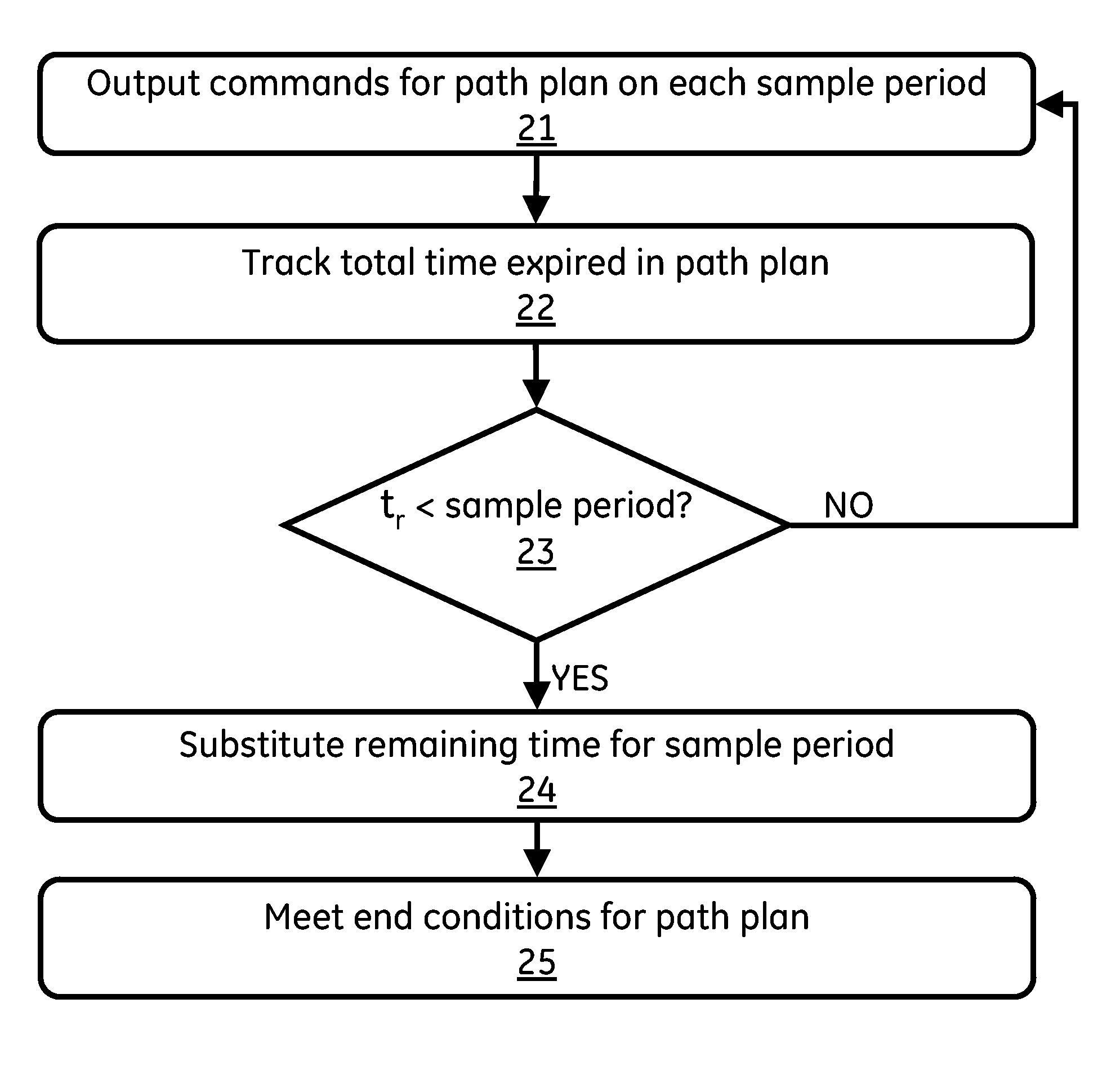
[0014]One embodiment of the present invention includes a method and system for path planning utilizing a continuous path plan implemented in a discrete time controller.

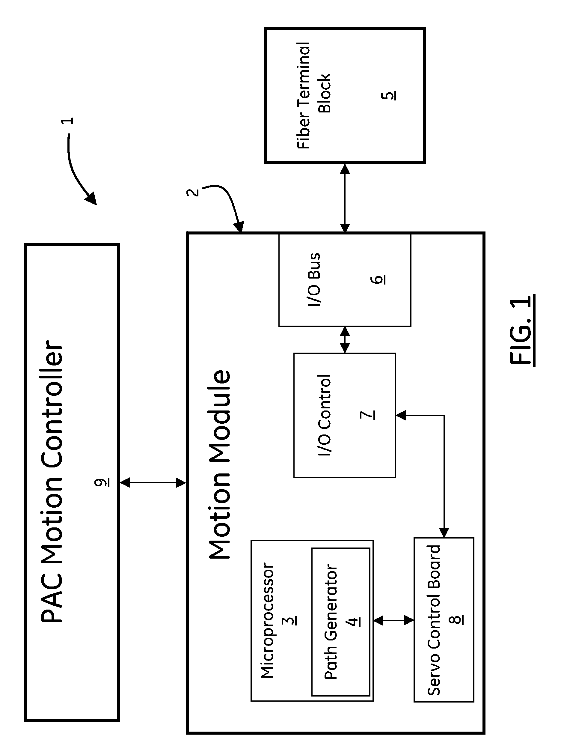
[0015]Referring now to FIG. 1, a block diagram of a Programmable Automation Controller (PAC) type motion system 1 for path planning is shown according to one embodiment of the present invention. The PAC system 1 includes a PAC system type motion controller 9, a PAC system type motion module (PMM) fiber terminal block 5 and a (PMM) motherboard 2 comprising a microprocessor subsystem 3. PMM motherboard 2 further includes several subsystems including a path generator 4. Path generator 4 is a firmware subsystem that runs on microprocessor 3 that is dedicated to path planning. Other firmware subsystems that support the functions of PMM motherboard 2 include a communication bus 6, such as a PCI backplane, and other associated hardware support functions.

[0016]PAC system 1 may include an input / output (I / O) module 7 for receiv...


PUM


Abstract

One embodiment of a system and method for meeting end conditions of a path plan utilizing a path generator that continuously generates commands for a path plan while tracking the total time expired in the path plan. The path generator computes the time remaining in the path plan and substitutes the remaining time for the length of the final sample period in the path plan when the length of the remaining time is less than the length of a full sample period.

Description

BACKGROUND OF THE INVENTION[0001]1. Field of the Invention[0002]The subject matter described herein relates generally to a system and method for meeting end conditions determined by a continuous time path planning method for motion control systems, more particularly path planners.[0003]2. Related Art[0004]Path planners or path generators typically comprise motion controllers that are used to control motors. The motors that employ path planning can be found in various industrial systems such as manufacturing, assembling, packaging and other capacities. These motors typically control the movements of elements such as drill bits or robotic arms. Path generators determine the movements of the controlled elements.[0005]Path generators use various kinetic path algorithms along with discrete time controllers. The use of discrete time controllers with continuous time path planning algorithms creates problems for meeting the end conditions of the path plan. The path plan is comprised of move...

Claims


Application Information

Patent Timeline
Patent Type & Authority Patents(United States)
IPC IPC(8): G06F17/00G06F19/00G05B19/00G05B13/00G05B11/01G05B19/19
CPCG05B19/416G05B2219/34208G05B2219/42244G05B2219/42255G05B2219/43018G05B2219/43065
Inventor MILLER, DANIEL H.MORRISON, WILLIAM LINDSAY
Owner INTELLIGENT PLATFORMS LLC
Why Eureka
Try Eureka