Touch display device, driving circuit, and driving method

a display device and driving circuit technology, applied in the direction of instruments, computing, electric digital data processing, etc., can solve the problems of insufficient image quality with a high resolution, increased cost of electronic components, and reduced image quality and touch sensitivity, so as to reduce the defect of an image of a line shape, the effect of stably executing display driving

Active Publication Date: 2021-05-11
LG DISPLAY CO LTD
View PDF21 Cites 8 Cited by
  • Summary
  • Abstract
  • Description
  • Claims
  • Application Information

AI Technical Summary

Benefits of technology

[0011]An objective of embodiments of the disclosure is to provide a touch display device, a driving circuit, and a driving method that can simultaneously stably execute display driving and touch driving.
[0012]Another objective of embodiments of the disclosure is to provide a touch display device, a driving circuit, and a driving method that can simultaneously stably execute display driving and touch driving using a display panel having touch sensors embedded therein.
[0013]Another objective of embodiments of the disclosure is to provide a touch display device, a driving circuit, and a driving method that can reduce an image defect of a line shape which may be caused by timing mismatch between a gate driving relevant signal and a touch electrode driving signal.
[0046]According to embodiments of the disclosure, it is possible to provide a touch display device, a driving circuit, and a driving method that can simultaneously stably execute display driving and touch driving.
[0047]According to embodiments of the disclosure, it is possible to provide a touch display device, a driving circuit, and a driving method that can simultaneously stably execute display driving and touch driving using a display panel having touch sensors embedded therein.
[0048]According to embodiments of the disclosure, it is possible to provide a touch display device, a driving circuit, and a driving method that can reduce an image defect of a line shape which may be caused by timing mismatch between a gate driving relevant signal and a touch electrode driving signal.

Problems solved by technology

In such a time-division driving system, considerably elaborate timing control is required for accurately performing display driving and touch driving at divided times in a time-division manner, and expensive electronic components may be required.
In the time-division driving system, both a display driving time and a touch driving time may be insufficient and thus there is a problem in that image quality and touch sensitivity decrease.
Particularly, there may be a problem in that image quality with a high resolution is not provided due to time-division driving.
Simultaneous execution of display driving and touch has been studied, but there is considerable technical difficulty in simultaneously executing display driving and touch driving.
However, there are problems with occurrence of an image defect and the like because touch driving is affected by display driving or display driving is affected by touch driving.
Particularly, such problems become severe when touch sensors (touch electrodes) are embedded in a display panel and are not easily solvable.

Method used


Image

  • Touch display device, driving circuit, and driving method
  • Touch display device, driving circuit, and driving method
  • Touch display device, driving circuit, and driving method

Examples


case 2

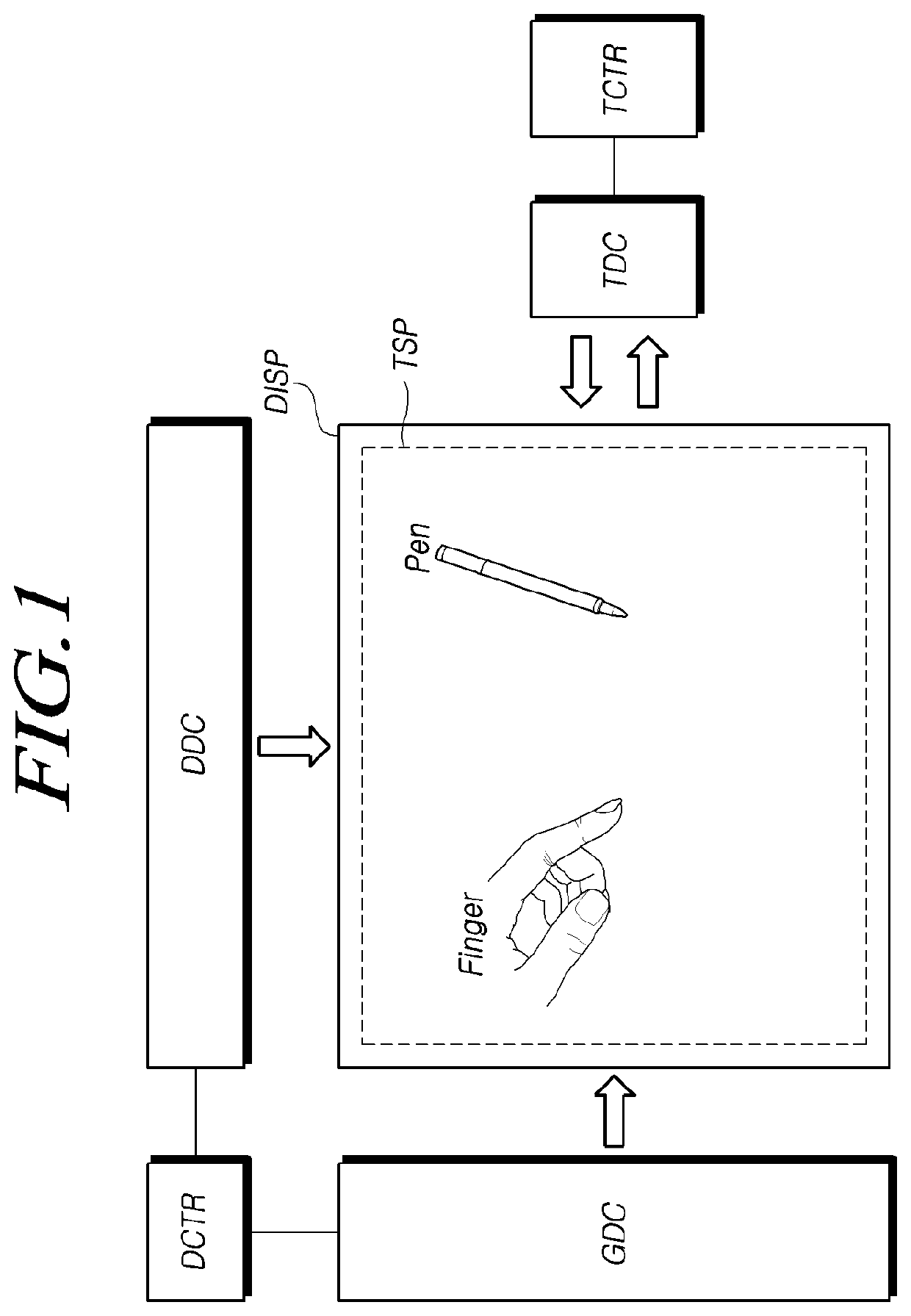
[0157]In Case 2 of time-free driving, the touch display device can perform only display driving.

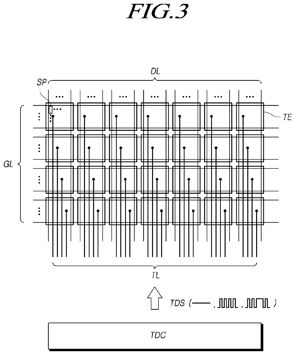
[0158]In Case 2, since the touch display device does not need to sense a touch of a finger, the touch display device does not perform general touch driving. That is, the touch display device does not supply the touch electrode driving signal TDS of a variable voltage to the plurality of touch electrodes TE which are disposed in the touch panel TSP.

[0159]In Case 2, the touch display device can supply the touch electrode driving signal TDS of a DC voltage. In the following description, the touch electrode driving signal TDS which is applied to the touch electrodes TE in Case 2 is referred to as a second touch electrode driving signal TDS2.

[0160]On the other hand, in Case 2, the touch display device can receive a pen signal output from a pen and sense the pen. The touch display device can acquire a result of pen sensing, a position, a tilt, and a pressure (a pen pressure) of a pen, or variou...

case 1

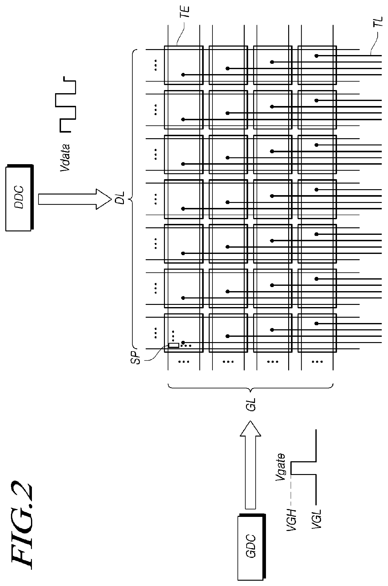
[0227]In Case 1 in which display driving and touch driving are simultaneously performed, when the first touch electrode driving signal TDS1 is output to the plurality of touch electrodes TE, load-free driving for reducing unnecessary parasitic capacitance from being formed between the plurality of touch electrodes TE and the plurality of data lines DL is required.

[0228]For this purpose, the data driving circuit DDC can supply a data signal Vdata for generating the same voltage variation state as the voltage variation state of the touch electrodes TE due to the first touch electrode driving signal TDS1 in the data lines DL to the data lines DL.

[0229]For this load-free driving, the data driving circuit DDC can use a gamma modulation technique.

[0230]More specifically, the data driving circuit DDC can convert an image digital signal into an image analog signal in response to the gamma reference voltage EGBI_M of a modulated signal pattern swinging with a predetermined amplitude and outp...


PUM


Abstract

A touch display device, a driving circuit, and a driving method are provided. An image defect which occurs when display driving and touch driving are simultaneously executed can be reduced by performing control such that a voltage level of a touch electrode driving signal (TDS) varies in a section other than a high-level period (Pon) of an ON-clock signal (ON_CLK) and / or a high-level period (Poff) of an OFF-clock signal (OFF_CLK).

Description

CROSS REFERENCE TO RELATED APPLICATION[0001]This application claims priority from the Republic of Korea Patent Application No. 10-2018-0170592, filed on Dec. 27, 2018, and the Republic of Korea Patent Application No. 10-2019-0062755, filed on May 28, 2019, each of which is hereby incorporated by reference in its entirety.BACKGROUNDField of Technology[0002]Embodiments of the present disclosure relate to a touch display device, a driving circuit, and a driving method.Discussion of the Related Art[0003]With advancement in information-oriented societies, requirements for touch display devices displaying an image have increased in various types, and various display devices such as a liquid crystal display device and an organic light emitting display device have been widely utilized in recent years.[0004]Among such display devices, there is a touch display device that provides a touch-based input system enabling a user to easily, intuitively, and conveniently input information or commands...

Claims


Application Information

Patent Timeline
Patent Type & Authority Patents(United States)
IPC IPC(8): G06F3/041G09G3/36G06F3/044
CPCG06F3/0416G06F3/0412G06F3/0446G09G3/3674G09G3/3685G09G2310/027G09G2310/0213G09G2310/08G09G2354/00G09G3/32G09G2310/0275G09G2320/0626G09G2320/0666G09G2360/141G06F3/04166G06F3/0443
Inventor KIM, SUNGCHULKIM, HOONBAEKIM, SUNYEOPKANG, SEONGKYU
Owner LG DISPLAY CO LTD
Why Eureka
Try Eureka