
GOA circuit driving method and driving device

a technology of array circuit and driving method, applied in the field of display technology, can solve the problems of high power consumption, and achieve the effect of maximizing the power consumption and feedthrough effect of goa circuit, and maximizing the power consumption and feedthrough

Active Publication Date: 2021-05-18
TCL CHINA STAR OPTOELECTRONICS TECH CO LTD
View PDF11 Cites 2 Cited by
  • Summary
  • Abstract
  • Description
  • Claims
  • Application Information

AI Technical Summary

Benefits of technology

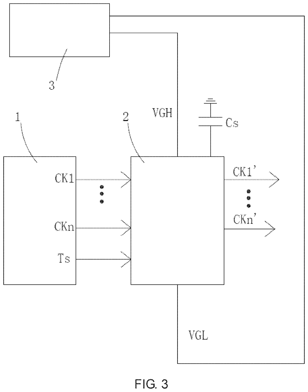
The present invention provides a method and device for driving a GOA circuit that reduces power consumption and feedthrough effect. This is achieved by configuring a buffer capacitor that keeps the transition level always halfway between the high and low voltage levels. This results in a maximization of reduction of power consumption and feedthrough effect of the GOA circuit.

Problems solved by technology

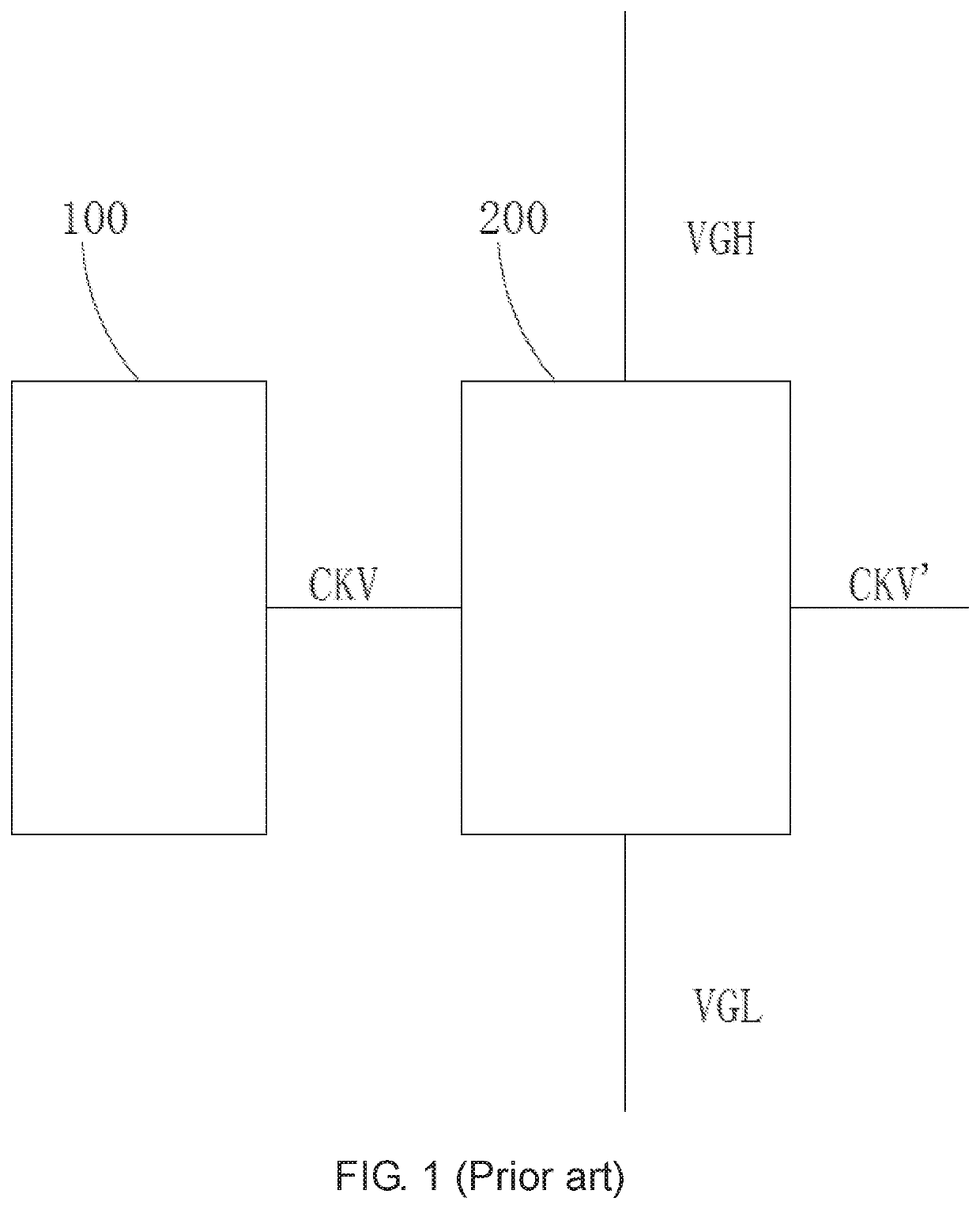
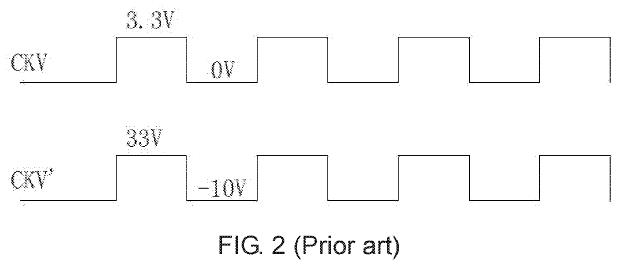
The two-state clock signal CKV′ leads to high power consumption and obvious feedthrough effect from the GOA circuit.

Method used


Image

  • GOA circuit driving method and driving device
  • GOA circuit driving method and driving device
  • GOA circuit driving method and driving device

Examples


Embodiment Construction

[0036]The following descriptions for the respective embodiments are specific embodiments capable of being implemented for illustrations of the present invention with referring to appended figures.

[0037]As shown in FIG. 5, a gate driver on array (GOA) circuit driving method according to the present invention includes the following steps.

[0038]Step S1: as shown in FIG. 3, providing a GOA circuit driving device, which includes a timing controller 1, a level shift IC 2, and a buffer capacitor Cs. The timing controller 1 is electrically connected to the level shift IC 2. A first terminal of the buffer capacitor Cs is electrically connected to the level shift IC 2 and a second terminal of the buffer capacitor Cs is electrically connected to ground. The level shift IC 2 is electrically connected to the GOA circuit.

[0039]The level shift IC 2 is electrically connected to a high voltage source VGH and a low voltage source VGL.

[0040]Specifically, the GOA circuit driving device also includes a ...


PUM


Abstract

The present invention teaches a GOA circuit driving method and a GOA circuit driving device. Through the configuration of a buffer capacitor electrically connected to the level shift IC, the level shift IC connects to the buffer capacitor and switches to the transition level during shifting the target clock signals from high to low level or from low to high level. Through the buffer capacitor, the present invention is able to keep the transition level always equal to one half of the sum of the low voltage and the high voltage, thereby maximizing reduction of power consumption and feedthrough effect of the GOA circuit.

Description

FIELD OF THE INVENTION[0001]The present invention is generally related to the field of display technology, and more particularly to a driving method and a driving device to a Gate Drive on Array (GOA) circuit.BACKGROUND OF THE INVENTION[0002]Active Matrix Liquid Crystal Displays (AMLCDs) are currently most common display devices. An AMLCD includes multiple pixels, each having a Thin Film Transistor (TFT) whose gate is connected to a scan line extended along a lateral direction, whose source is connected to a data line extended along a vertical direction, and whose drain is connected a corresponding pixel electrode. By applying appropriate voltage to a scan line, all TFTs connected to the scan line are turned on and data signals on the data lines are written into the pixel electrodes, thereby showing an image.[0003]A type of display panel using AMLCD has the Gate Drive on Array (GOA) structure where Gate Drive IC is integrated on the TFT array substrate so as to achieve the line-by-l...

Claims


Application Information

Patent Timeline
Patent Type & Authority Patents(United States)
IPC IPC(8): G09G3/36
CPCG09G3/3677G09G2300/0842G09G2300/0871G09G2310/0289G09G2310/08G09G2320/0219G09G2330/021
Inventor GAO, XIANG
Owner TCL CHINA STAR OPTOELECTRONICS TECH CO LTD
Learn More