Methods of treatment of viral diseases

Active Publication Date: 2021-05-25
SOFTHALE NV
14 Cites 0 Cited by

AI-Extracted Technical Summary

Problems solved by technology
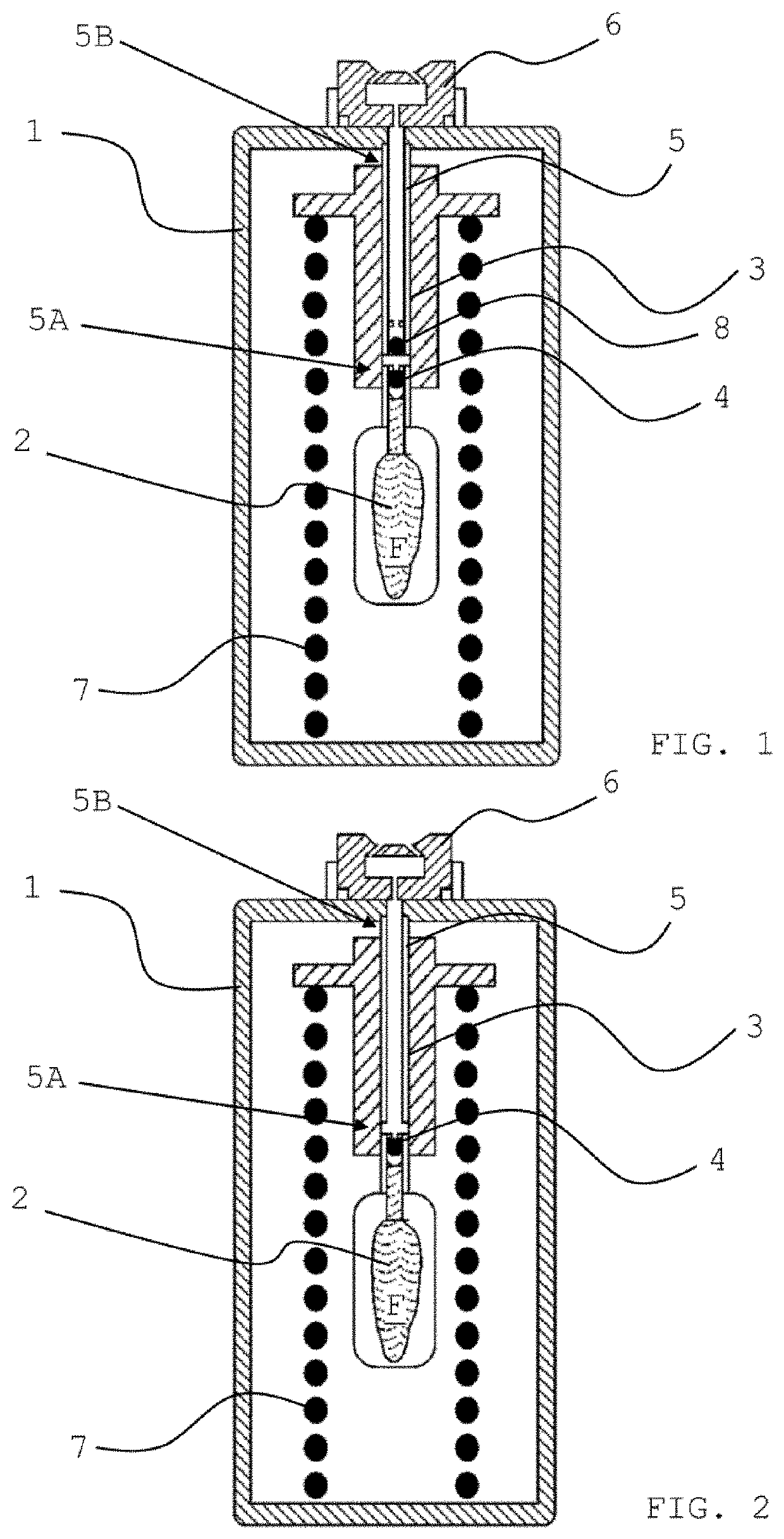
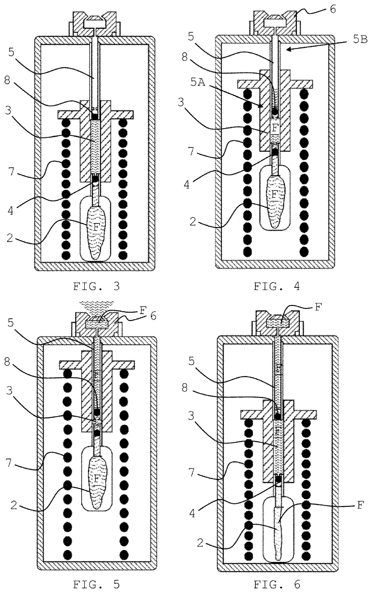
Despite these efforts, soluble, liquid formulations of remdesivir have not been developed for treating viral infectio...

Method used

[0019]The term ‘treatment’ as used herein, means administration of the compound or composition to a subject to at least ameliorate, reduce or suppress existing signs or symptoms of the infection, disease, disorder or condition experienced by the subject.
[0088]In some embodiments, the riser pipe of the pumping unit of the inhalation device of the invention is arranged downstream of the cylinder, and it is preferably firmly affixed to the user-facing side of the housing such as to be immobile relative to the housing or at least to the part of the housing which comprises the user-facing side of the housing. For the avoidance of doubt, in this context firmly fixed means either directly or indirectly (i.e., via one or more connecting parts) fixed such as to prevent relative movement between the respective parts. As the nozzle is also immobile relative to the housing or the respective part of the housing, the riser pipe is also immobile relative to the nozzle, and the pumping action is affected by the longitudinal movement of the hollow cylinder. A propulsive movement of the cylinder, which is arranged in an upstream position relative to the riser pipe, results in a decrease of the volume of the pumping chamber, and a repulsive movement of the cylinder results in an increase of the volume. In other words, the riser pipe maintains its position relative to the housing, and the hollow cylinder can alter its position relative to the housing, and in particular, along a longitudinal axis of the same, such as to perform a piston-in-cylinder-type movement of the immobile riser pipe in the moveable cylindrical member.
[0090]A key advantage of the described preferred inhalation device is that the passage between pumping chamber and fluid reservoir can be designed with less restrictions with respect to its dimensions. It is, for example, possible to accommodate a significantly larger inlet valve (also referred to as check valve), which is easier to manufacture since it does not have to be contained within a narrow riser pipe. Instead, the arrangement allows the use of a check valve whose size is only restricted by the interior size of the housing or the dimensions of the means for storing potential energy. In other words, the diameters of the valve, the riser pipe and—if used—the reservoir pipe do not need to match each other. Furthermore, since no movable piston needs to be connected to the fluid reservoir, the component which provides the fluid connection to the reservoir can be designed independently of the moveable component, i.e., the hollow cylinder, allowing the individual parts to be adapted to suit their respective individual functions. In this respect, the described pump arrangement provides for higher design flexibility because the moveable hollow cylinder, due to its robust structure and dimensions, provides better opportunities for designing a mechanically stable connection with the reservoir than would a less robust moveable riser pipe. Also, the connection between the hollow cylinder and the fluid reservoir can be designed with a larger diameter, such that higher flow velocities and fluid viscosities become feasible. Further, a support for the reservoir can be integrated into any component that comprises the cylinder. Additionally, any vent for pressure equilibration of the reservoir can be moved away from the reservoir body itself to a connector which forms an interface between reservoir and hollow cylinder, thus facilitating construction and avoiding the necessity to provide an essentially “open” reservoir body.
[0102]As mentioned, one of the advantageous effects is that an inlet valve having relativel...

Benefits of technology

[0102]As mentioned, one of the advantageous effects is that an inlet valve having relatively large dimensions may be accommodated in this position, i.e., at the upstream end of the pumping chamber. This is particularly beneficial as it allows for large dimensions of the fluid conduit(s) within the valve, thus enabling high fluid velocities which translate into a rapid filling of the pumping chamber during the priming of the inhalation device. Moreover, the use of liquids having a higher viscosity than ordinary liquid formulations for inhalation, such as highly concentrated solutions of soluble active ingredients, become feasible for inhalation therapy.
[0103]According to a further preferred embodiment, the inlet valve may be adapted to open only when the pressure difference between the upstream and the downstream side of the valve, i.e., the fluid reservoir side and the pumping chamber side, is above a predefined threshold value, and remains closed as long as the pressure difference is below the threshold value. The term ‘pressure difference’ as used in this context means that, irrespective of the absolute pressure values, only the relative pressure difference between the two sides is relevant for determining whether the valve blocks or opens. If, for example, the pressure on the upstream (reservoir) side is already positive (e.g., 1.01 bar due to thermal expansion), but the pressure on the downstream (pumping chamber) side is ambient pressure (1.0 bar, no activation of the device), the pressure difference (here: 0.01 bar) is below the threshold value (e.g., 20 mbar), which allows the valve to stay closed even when subject to a positive pressure in opening direction. This means that the check valve remains closed until the threshold pressure is met, thus keeping the passage between reservoir and pumping chamber safely shut e.g. when the inhalation device is not in use. Examples for threshold pressure differences are in the range of 1 to 1000 mbar, and more preferably between about 10 and about 500 mbar, or between about 1 and about 20 mbar.
[0104]When actuating the inhalation device, as the means for storing potential energy alters its state from a locked state to an unlocked state, energy may be released which effects the cylinder to perform its propulsive longitudinal movement, significant pressure is built up in the pumping chamber. This generates a marked pressure difference (due to a high pressure in the pumping chamber and a substantially lower pressure in the fluid r...

Abstract

The present invention provides for a method for the treatment of a viral disease, disorder or condition in a subject, the method comprising the step of administering to said subject a medically active liquid in nebulized form by inhalation, wherein the medically active liquid comprises remdesivir or a pharmaceutically acceptable salt thereof and wherein the medically active liquid is administered in nebulized form using an inhalation device.

Application Domain

Organic active ingredientsDispersion delivery +8

Technology Topic

Pharmaceutical medicineViral disease +5

Image

  • Methods of treatment of viral diseases
  • Methods of treatment of viral diseases
  • Methods of treatment of viral diseases

Examples

  • Experimental program(2)

Example

[0153]For Example 1, solutions of water and ethylene glycol were prepared combining the two solvents at room temperature. For Example 2, solutions of remdesivir in ethanol (100%) were prepared by dissolving remdesivir in ethanol at room temperature. For Example 2, a solution of remdesivir in ethanol:water (70:30% w/w) was prepared by dissolving remdesivir in ethanol at room temperature and adding water to the solution. Each solution was dispensed using an embodiment of a soft mist inhaler as disclosed herein. Particle size distributions of the dispensed solutions were measured using a Malvern Spraytec® instrument.
Example 1
[0154]Solutions of water and ethylene glycol were prepared to mimic the viscosity of a high molecular weight compound such as remdesivir at concentrations of 5%, 10%, 15%, 20%, and 25% (wt. % of compound in solution). The wt/wt % values of ethylene glycol and water in each solution are summarized in Table 1.
[0155] TABLE 1 Dynamic Relative Water/Ethylene Sample Viscosity Density Glycol ratio (% w/w) PR 5% 1.66 0.8174 90% H2O/10% EG PR 10% 1.93 0.8269 80% H2O/20% EG PR 15% 2.15 0.8364 75% H2O/25% EG PR 20% 2.47 0.8458 73% H2O/27% EG PR 25% 2.91 0.8551 70% H2O/30% EG
[0156]Solutions were dispensed using an embodiment of a soft mist inhaler as disclosed herein at room temperature. The dispensing parameters and particle size distribution results are summarized in Table 2 and FIG. 7. The term “event duration” refers to entire spray duration in seconds (s) when the solution is dispensed.
[0157] TABLE 2 PR 5% PR 10% PR 15% PR 20% PR 25% Mean Mean Mean Mean Mean Parameters (n = 6) Stdev (n = 6) Stdev (n = 6) Stdev (n = 6) Stdev (n = 6) Stdev Event duration/s 2.34 0.15 3.95 0.00 3.95 0.00 3.96 0.00 3.96 0.01 Dv10/μm 1.19 0.02 1.10 0.03 1.24 0.02 1.40 0.03 1.57 0.03 Dv50/μm 2.20 0.05 2.10 0.07 2.49 0.10 2.78 0.09 3.26 0.12 Dv90/μm 4.22 0.17 4.48 0.16 5.14 0.34 5.67 0.29 6.87 0.52

Example

Example 2
[0158]Solutions of remdesivir in ethanol (100%) and ethanol:water (70:30% w/w) were prepared at concentrations of approximately 3.56, 5.08, 7.63, and 10.17 mg ml. Solutions were dispensed using an embodiment of a soft mist inhaler as disclosed herein at room temperature. The dispensing parameters and particle size distribution results are summarized in Table 3 and FIG. 8. Addition of water increases the particle size.
[0159] TABLE 3 Spray duration Dv10 Dv50 Dv90 Ethanol Formulation (s) (μm) (μm) (μm) Span content REM 10.17 1.95 1.11 1.96 3.54 1.24 100% REM 7.63 1.70 1.14 1.92 3.31 1.14 100% REM 5.08 1.72 1.13 1.9 3.26 1.12 100% REM 3.56 2.53 1.71 3.29 6.27 1.38 70%

PUM

PropertyMeasurementUnit
Concentration0.01kg / L
Concentration0.03kg / L
Volume1.0E-6L

Description & Claims & Application Information

We can also present the details of the Description, Claims and Application information to help users get a comprehensive understanding of the technical details of the patent, such as background art, summary of invention, brief description of drawings, description of embodiments, and other original content. On the other hand, users can also determine the specific scope of protection of the technology through the list of claims; as well as understand the changes in the life cycle of the technology with the presentation of the patent timeline. Login to view more.

Similar technology patents

Production of high viscosity index lube base oils

ActiveUS20090261015A1high viscosity
Owner:EXXON RES & ENG CO

Aminopyridinium ionic liquids

ActiveUS7687513B1high viscosityenhance viscosity
Owner:UNIV OF NOTRE DAME DU LAC +1

Plastic label adhesive and preparation method thereof

Owner:苏州市丛岭胶粘剂有限公司

Clean fracturing fluid thickening agent and preparation method thereof

InactiveCN104231156AGood shear resistancehigh viscosity
Owner:CNPC BOHAI DRILLING ENG

Fuel supply device and fuel supply method

ActiveUS20110168137A1high viscositysimple structure
Owner:YANMAR POWER TECHNOLOGY CO LTD

Classification and recommendation of technical efficacy words

  • high viscosity
Why Eureka
Try Eureka