
Eureka
For R&D, Eureka makes reading and utilizing patents & technical documents easy.
Eureka AIR
Designed for self-driven R&D workflows. Generate viable solutions, solve complex R&D challenges, empower your innovation with AI.

Eureka Materials
Designed for material experts only. Revolutionize your material R&D, from search, analyze, to developing new materials.

TechResearch
Generate reliable direction feasibility study reports for your R&D in just a few steps.

TechSeek
Discover and master advanced knowledge NOW. Basics, ideas, possibilities, all at once.

TechMind
As an expert in R&D Theories, TechMind can generates customized viable solutions instantly.

TechRisk
Analyze your overall solution with one click, know your potential R&D risks in advance.

TechMonitor
Get weekly tech updates, stay abreast of the latest tech innovations and key insights.
Auger stand for digger derrick
- Summary
- Abstract
- Description
- Claims
- Application Information
AI Technical Summary
Benefits of technology
Problems solved by technology
Method used
Image

Examples
second embodiment
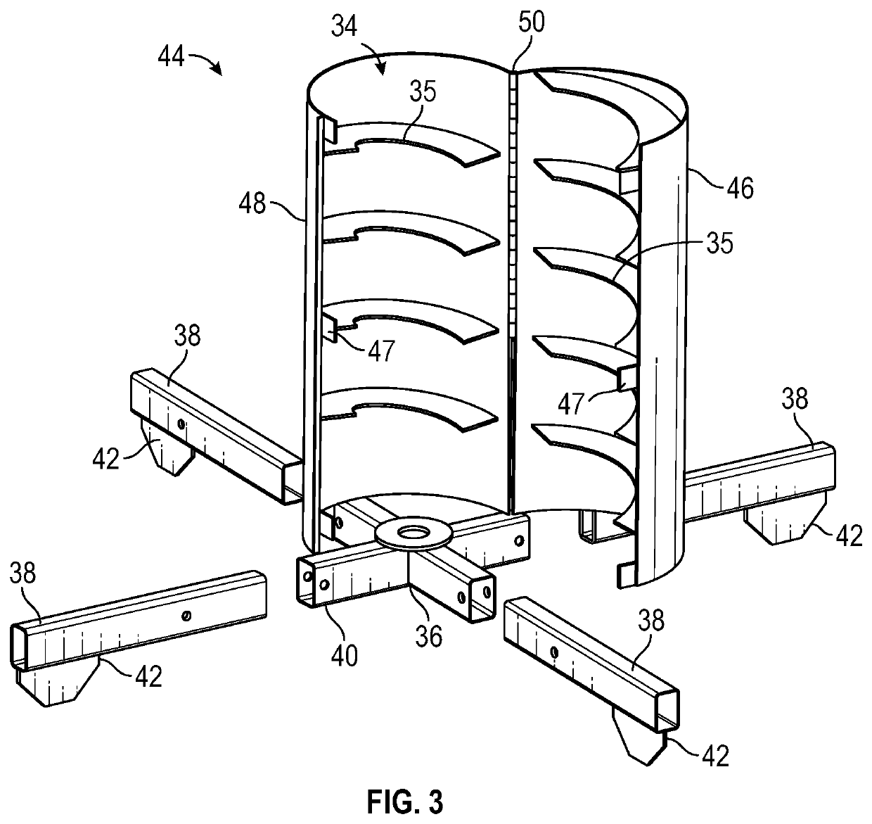
[0033]FIG. 3 shows an exploded view of a hinged auger stand 44. The hinged auger stand 44 comprises a first wall portion 46 rotatably attached to a second wall portion 48 at a rotatable hinge joint 50. The landing 34 may be distributed on each of the first wall portion 46 and the second wall portion 48 as shown. The hinged auger stand 44 can be opened, as shown, and closed by rotating the first wall portion 46 and / or the second wall portion 48 about the rotatable hinge joint 50. Although two wall portions are shown, the hinged auger stand may include additional wall portions and additional hinges. In some embodiments, it may be desirable to use the hinged auger stand 44 because it can be quickly placed over and removed from the auger 24. In some such embodiments, at least one operator may open / close the hinged auger stand 44.
[0034]In some embodiments, the hinged auger stand 44 may include an automatic opening and closing mechanism (not shown), such that the operator can remotely con...
third embodiment
[0037]FIG. 4A shows a collapsible auger stand 52. The collapsible auger stand 52 comprises a plurality of foldable members 54 attached to the respective plurality of legs 38 by a plurality of pivoting slides 56. The pivoting slides 56 allow the legs 38 to pivot, such that they may be folded into the foldable members 54. In such embodiments, the plurality of legs 38 may be joined using a center hinge ring 58. The center hinge ring 58 joins the plurality of legs 38 while also allowing rotation of the legs 38. In some embodiments, the collapsible auger stand 52 comprises three legs 38 to support the collapsible auger stand 52, as shown. The collapsible auger stand 52 further comprises a plurality of rollers 60 attached along each of the foldable members 54 by attachment arms 57. Here, the attachment arms 57 may be secured to the foldable members 54 using fasteners, such as pins, screws, bolts, or any other suitable mechanical fasteners. In some embodiments, the foldable members 54 comp...
fourth embodiment
[0041]FIG. 5 shows a slotted auger stand 64. The slotted auger stand 64 comprises slotted wall section 66 including a plurality of slots 68. The plurality of slots 68 reduce the weight of the slotted auger stand 64, and create ventilation to remove heat associated with use of the slotted auger stand 64. The slots 68 may be any shape or size. In some embodiments, the slotted wall section 66 includes a plurality of fastener holes 70 for receiving fasteners therein, such that the plurality of rollers 60 may be fastened to the slotted wall section 66. In such embodiments, the rollers 60 are secured directly to the slotted wall section 66 by placing a fastener, which may be any known suitable fastener, through the fastener hole 70. The fastener may extend through the fastener hole 70 and be secured directly to the roller 60. For example, in some embodiments, a bolt may extend through the fastener hole 70 and screw into a threaded portion within a bearing of the roller 60. When in use, th...
PUM
 Abstract
Description
Claims
Application Information
 - R&D Engineer
- R&D Manager
- IP Professional
- Industry Leading Data Capabilities
- Powerful AI technology
- Patent DNA Extraction
Browse by: Latest US Patents, China's latest patents, Technical Efficacy Thesaurus, Application Domain, Technology Topic, Popular Technical Reports.
© 2024 PatSnap. All rights reserved.Legal|Privacy policy|Modern Slavery Act Transparency Statement|Sitemap|About US| Contact US: help@patsnap.com