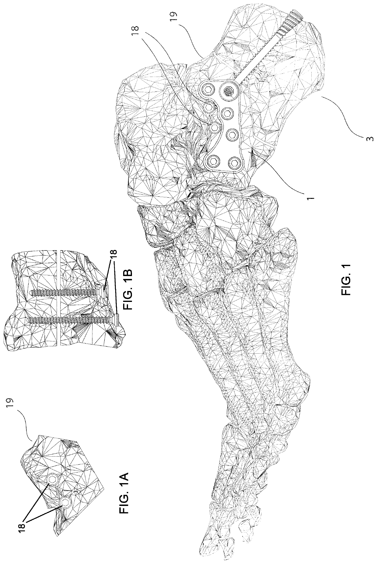
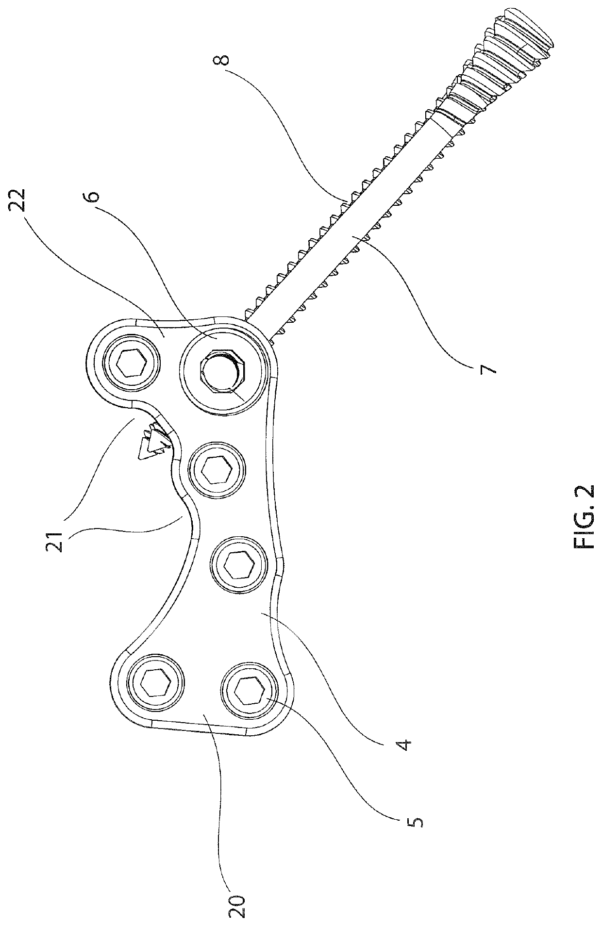
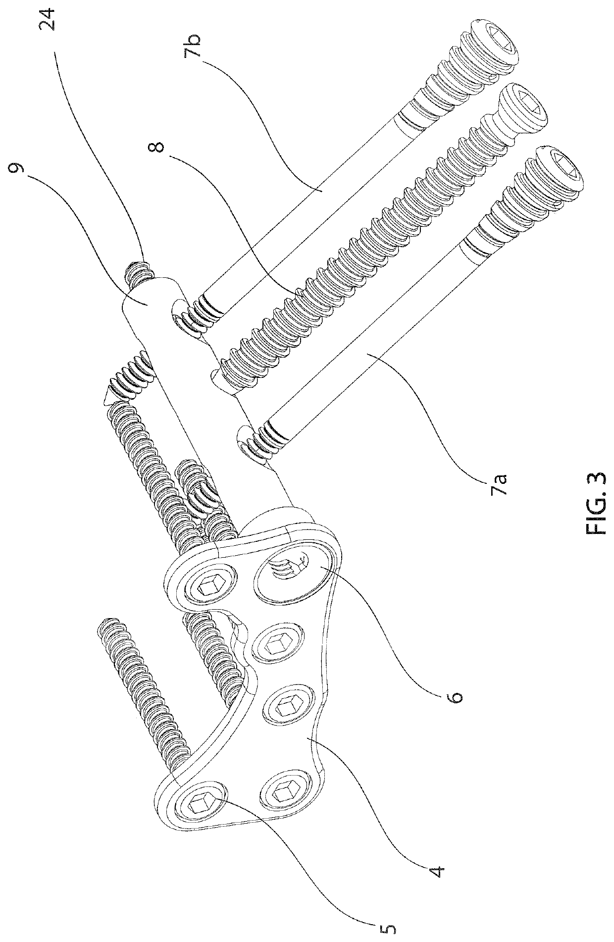
Calcaneal cross medullary plate

a technology of medullary plate and calcaneal cross, which is applied in the direction of bone plate, internal osteosythesis, osteosythesis device, etc., can solve the problems of poor wound healing and infection, disruption of the blood supply to the bone, and no good data to support immediate weight bearing with any current device, so as to reduce the elevation of soft tissue, less devitalization, and less scarring

Active Publication Date: 2021-06-15
EXTREMITY MEDICAL
View PDF21 Cites 2 Cited by
  • Summary
  • Abstract
  • Description
  • Claims
  • Application Information

AI Technical Summary

Benefits of technology

[0009]It is an object of the present invention to reduce elevation of soft tissue, leading to less devitalization, less scarring, improved range of motion, enhanced function, and a lower infection rate compared to traditional extensile lateral plating.
[0010]It is a further object of the present invention to allow for accurate, stable joint restoration which may lead to a lower risk of post traumatic arthritis.

Problems solved by technology

Some of the main complications of open treatment and internal fixation of calcaneus fractures are poor wound healing and infection.
Secondary complications include stiffness due to extensive scarring after internal fixation requiring extensive elevation of soft tissue envelopes.
Although some of the existing devices assert that a patient can bear weight early after internal fixation, there is no good data to support immediate weight bearing with any of the current devices.
This extensive elevation of soft tissue off the calcaneal bone may lead to disruption of the blood supply to the bone and may compromise the viability of the soft tissues.
Such results then lead to the higher risk of scarring, poor wound healing, and infections.
However, such solution does not typically allow for adequate reduction and stabilization of the posterior facet, which is the articular surface of the subtalar joint.
If the joint surface is not accurately and securely fixated, the risk of developing post traumatic arthritis is greatly increased.
However, the intramedullary device and the independent lag screws may not be coupled together.
This allows for accurate reduction of the joint and the body of the calcaneus, but does not provide for adequate axial stability to permit early weight bearing.
The current intramedullary products on the market do not allow for accurate joint fixation.
The current screw and plate products on the market usually lead to excessive soft tissue injury and higher wound healing and infection risks.

Method used


Image

  • Calcaneal cross medullary plate
  • Calcaneal cross medullary plate
  • Calcaneal cross medullary plate

Examples


Embodiment Construction

[0030]The invention may be understood more readily by reference to the following detailed descriptions of embodiments of the invention. However, techniques, systems, and operating structures in accordance with the invention may be embodied in a wide variety of forms and modes, some of which may be quite different from those in the disclosed embodiments. Also, the features and elements disclosed herein may be combined to form various combinations without exclusivity, unless expressly stated otherwise. Consequently, the specific structural and functional details disclosed herein are merely representative. Yet, in that regard, they are deemed to afford the best embodiment for purposes of disclosure and to provide a basis for the claims herein, which define the scope of the invention. It must be noted that, as used in the specification and the appended claims, the singular forms “a”, “an”, and “the” include plural referents unless the context clearly indicates otherwise.

[0031]The invent...


PUM


Abstract

Apparatus and method for securely fixating an anterior portion of a calcaneus to a reduced posterior facet portion of the calcaneus, using a plate that may allow for stable fixation between the anterior calcaneus, the reconstructed posterior facet, and the posterior tuberosity, and a barrel that may be rotated into the best position to allow posterior screws to enter the best quality bone in the posterior tuberosity. The appropriate height may be set by rotating a push screw, thereby engaging the barrel, and pushing the posterior tuberosity distally.

Description

CROSS REFERENCE TO RELATED APPLICATION[0001]This application claims the benefit of U.S. Provisional Application No. 62 / 470,472, filed Mar. 13, 2017. The entire contents of that application are incorporated herein by reference.FIELD OF THE INVENTION[0002]This invention relates to the field of implant devices for bone fixation.BACKGROUND OF THE INVENTION[0003]The calcaneus is the most frequently fractured tarsal bone. In the majority of cases, the calcaneus breaks into three main fragments, namely the anterior, posterior facet, and posterior tuberosity. The posterior facet is the main joint surface and is often broken into two or more pieces. To successfully repair a calcaneus that is fractured, the posterior facet joint surface typically should be accurately reduced and securely fixated. The posterior facet is then typically securely fixated to the anterior portion and the posterior tuberosity, restoring the normal alignment of the body of the calcaneus. The majority of calcaneus fra...

Claims


Application Information

Patent Timeline
Patent Type & Authority Patents(United States)
IPC IPC(8): A61B17/80A61B17/72
CPCA61B17/7233A61B17/8061A61B17/7291
Inventor STEINLAUF, STEVEN D.
Owner EXTREMITY MEDICAL
Why Eureka
Try Eureka