
Numerical control device

a control device and numerical technology, applied in the direction of program control, electric programme control, instruments, etc., can solve the problems of unnecessarily increasing machining time, affecting the creation of machining programs, and inappropriate operation of machine tools

Active Publication Date: 2021-06-29
FANUC LTD
View PDF5 Cites 0 Cited by
  • Summary
  • Abstract
  • Description
  • Claims
  • Application Information

AI Technical Summary

Benefits of technology

[0008]With the method described in Patent Document 1, it is necessary for the user to write the lookahead stop code at the appropriate position of the machining program. In other words, with the method described in Patent Document 1, if the user is unable to insert the lookahead stop code at the required position, operation of the machine tool becomes inappropriate, and the machining time increases unnecessarily if the user inserts the lookahead stop code at an unnecessary position. In this way, the method described in Patent Document 1 requires a high-level of understanding of the machining program by the user, and complicates creation of the machining program. For this reason, a numerical control device is desired which can perform the appropriate lookahead processing even without the user's instruction.
[0010]A numerical control device according to an aspect of the present disclosure can perform the appropriate lookahead processing even without a user's instruction.

Problems solved by technology

In other words, with the method described in Patent Document 1, if the user is unable to insert the lookahead stop code at the required position, operation of the machine tool becomes inappropriate, and the machining time increases unnecessarily if the user inserts the lookahead stop code at an unnecessary position.
In this way, the method described in Patent Document 1 requires a high-level of understanding of the machining program by the user, and complicates creation of the machining program.

Method used


Image

  • Numerical control device
  • Numerical control device
  • Numerical control device

Examples


Embodiment Construction

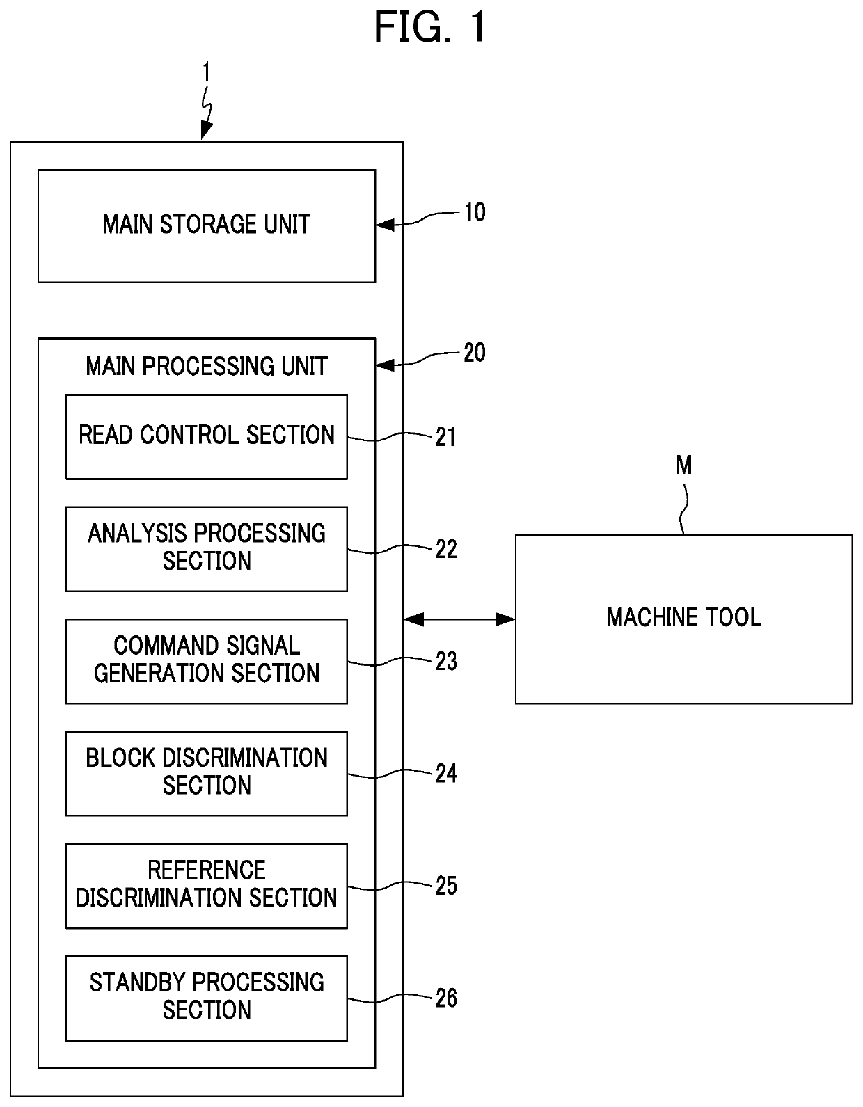
[0014]Hereinafter, an embodiment of a numerical control device according to the present disclosure will be explained while referencing the drawings. FIG. 1 shows a numerical control device 1 according to the embodiment of the present disclosure. The numerical control device 1 controls operation of a plurality of drive axes of a machine tool M including a plurality of axes based on a machining program.

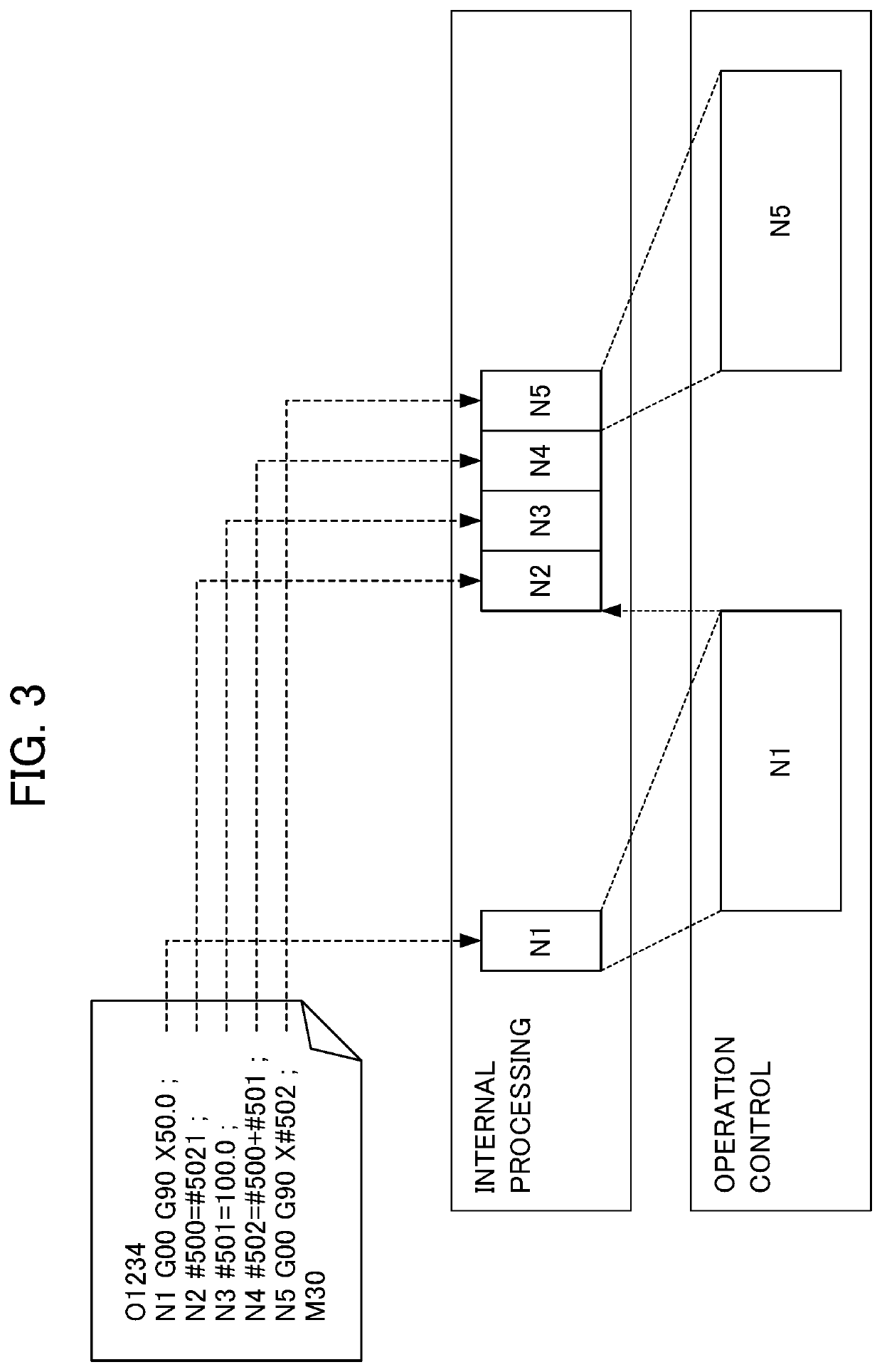
[0015]The machining program includes a plurality of blocks. In the blocks of the machining program, there exists an output block including an output command to output a command signal to the machine tool M, and an internal processing block not including an output command. The output block is also called an NC statement due to writing a command that controls the machine tool M. The internal processing is macro processing which mainly handles variables. For this reason, the internal processing block is also called a macro statement. In this internal processing block, a reference block inc...


PUM


Abstract

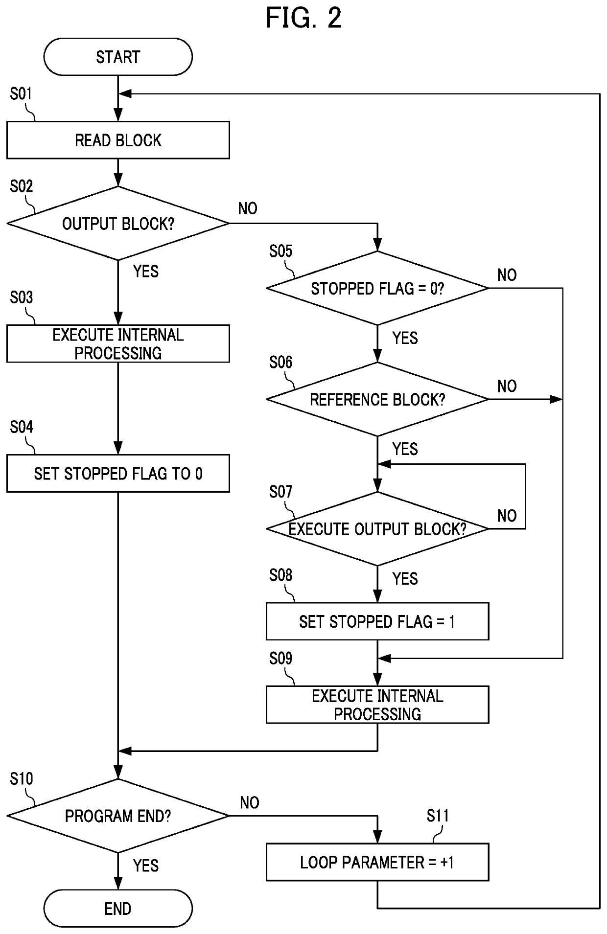
A numerical control device according to the present disclosure includes: a read control unit which reads a plurality of blocks of a machining program in order; an internal processing section which performs internal processing in accordance with a block read by the read control unit; an operation control section which generates a command signal for a machine tool based on results of internal processing; an output block discrimination section which discriminates whether the block read by the read control unit is an output block including an output command, or an internal processing block not including the output command; a reference block discrimination section which discriminates whether the internal processing block is a reference block including a command to reference information which is inputted externally; and a standby processing section which in a case of the internal processing block being the reference block, causes the internal processing section to stop the internal processing in accordance with the reference block, until execution of control of the machine tool completes based on the output block which is written nearest prior to the reference block.

Description

[0001]This application is based on and claims the benefit of priority from Japanese Patent Application No. 2019-121328, filed on 28 Jun. 2019, the content of which is incorporated herein by reference.BACKGROUND OF THE INVENTIONField of the Invention[0002]The present invention relates to a numerical control device.Related Art[0003]Numerical control devices that control the operation of a machine tool in accordance with a machining program consisting of a plurality of blocks are widely used. The machining program can include not only blocks writing commands to make the machine tool operate, but also blocks causing information acquisition and computation for deciding operation of the machine tool to be executed in the numerical control device.[0004]In addition, the numerical control device, even in a case of executing a block of a machining program writing a command causing the machine tool to operate, must perform pre-processing for calculating the detailed operation corresponding to ...

Claims


Application Information

Patent Timeline
Patent Type & Authority Patents(United States)
IPC IPC(8): G05B19/401G05B19/4155G05B19/404G05B19/18G05B19/406
CPCG05B19/4015G05B19/182G05B19/404G05B19/406G05B19/4155G05B2219/34095G05B19/41
Inventor SAIJO, YOSHINORI
Owner FANUC LTD
Learn More