
Vehicle air-conditioning system

a technology for air conditioning systems and vehicles, which is applied to vehicle components, vehicle heating/cooling devices, transportation and packaging, etc., can solve the problems of difficult to secure the air conditioning case b>10/b> in the interior of the vehicle becomes larger in size, and the interior space of the vehicle becomes difficult to secure. achieve the effect of maximizing the interior space of the vehicle, reducing the size of the distribution duct, and improving the comfort of the interior of the vehicl

Active Publication Date: 2021-07-06
HANON SYST
View PDF21 Cites 3 Cited by
  • Summary
  • Abstract
  • Description
  • Claims
  • Application Information

AI Technical Summary

Benefits of technology

The air conditioning system for a vehicle described in this patent improves the comfort of the vehicle by delivering warm air through the floor vent and cold air through the face vent, preventing temperature reversal. The system also reduces the size of the distribution duct and maximizes the interior space of the vehicle.

Problems solved by technology

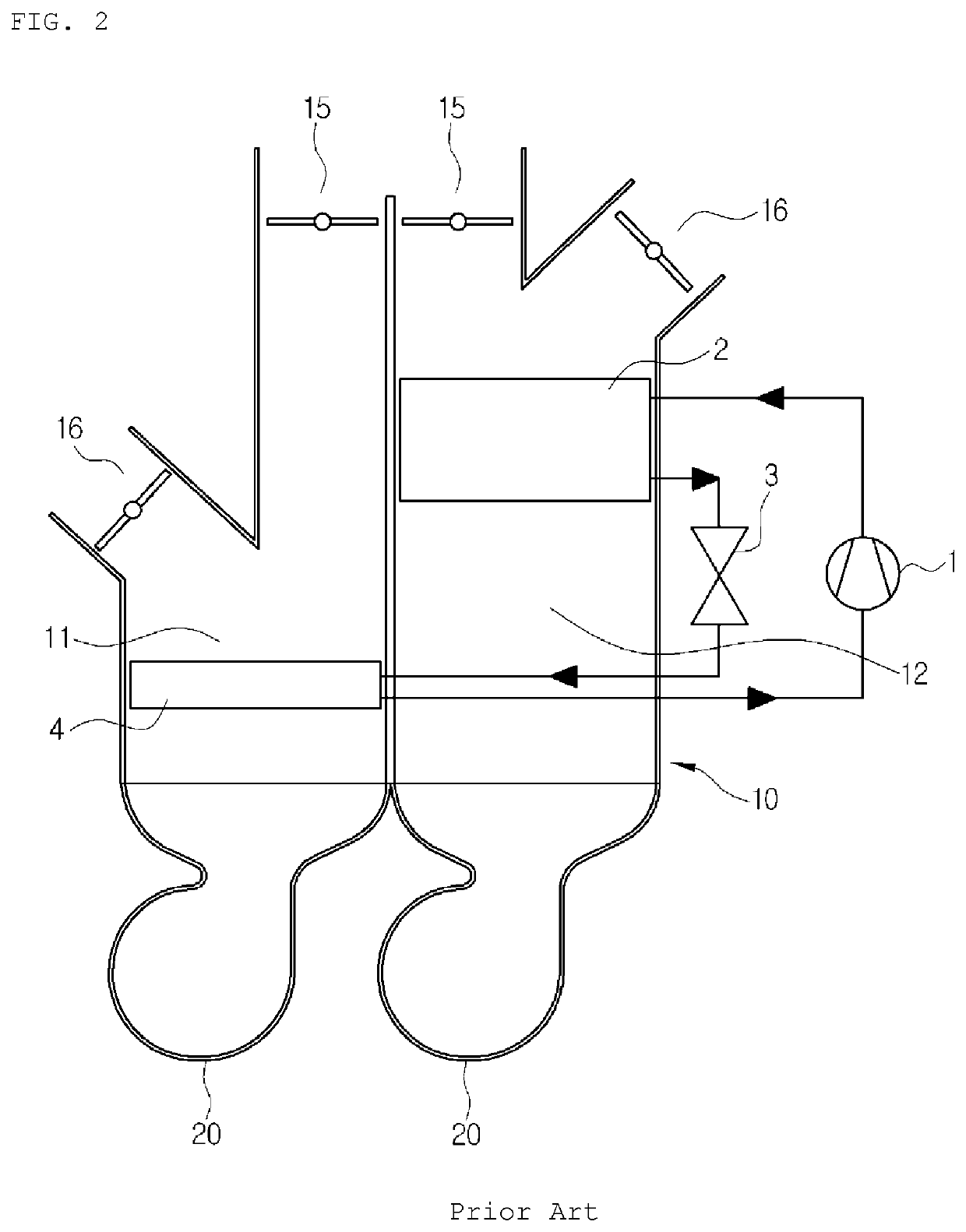
However, the conventional air conditioning system has a disadvantage in that it is difficult to secure an interior space of the vehicle because the air-conditioning case 10, which has the evaporator 4 and the condenser 2 mounted therein, and the blower (20) are mounted in the interior of the vehicle relative to the dash panel.
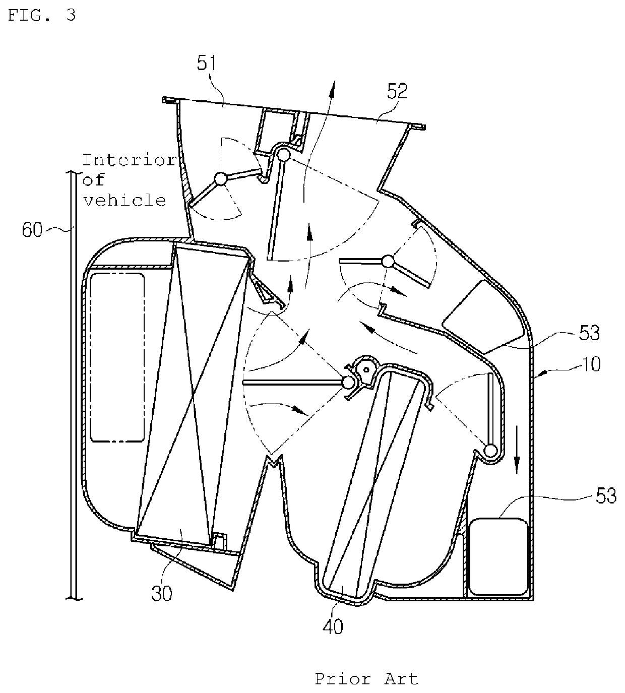
However, the conventional air-conditioning case 10 has several disadvantages in that the air-conditioning case 10 arranged in the interior of the vehicle becomes larger in size because the floor vent 53 is formed in the air-conditioning case 10 to be far from the dash panel 60, and in that it is difficult to secure the interior space of the vehicle.

Method used


Image

  • Vehicle air-conditioning system
  • Vehicle air-conditioning system
  • Vehicle air-conditioning system

Examples


Embodiment Construction

[0030]Reference will be now made in detail to preferred embodiments of the present invention with reference to the attached drawings.

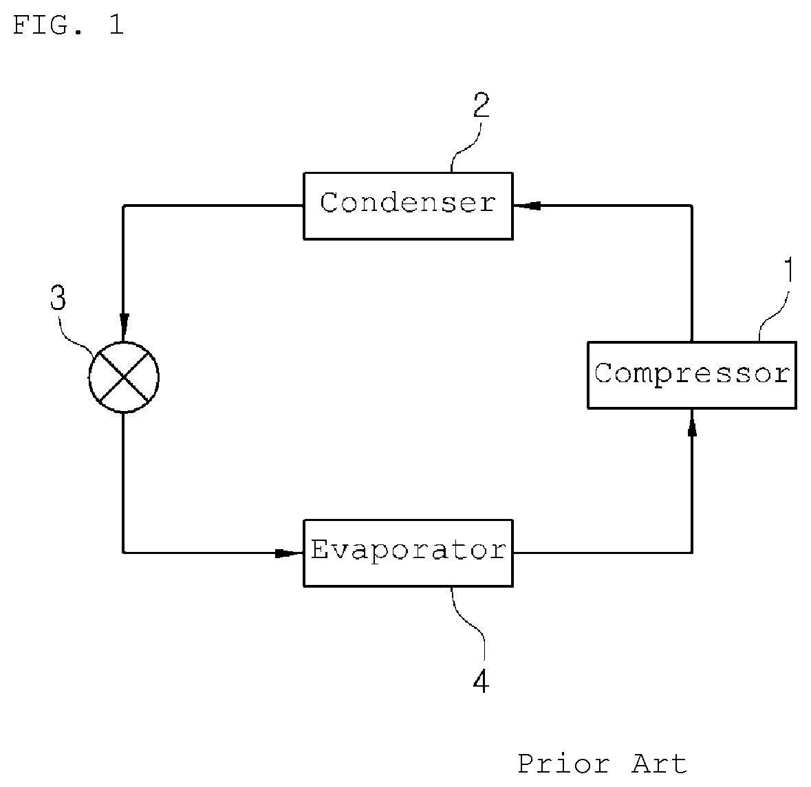
[0031]As shown in the drawings, an air conditioning system for a vehicle according to the present invention includes a compressor (not shown), a condenser 102, expansion means (not shown) and an evaporator 104, which are connected with one another in order through a refrigerant circulation line (not shown), so as to carry out cooling through the evaporator 104 and carry out heating through the condenser 102.

[0032]First, the compressor inhales and compresses vapor-phase refrigerant of low-temperature and low-pressure discharged from the evaporator 104 while operating by receiving a driving force from a power supply, such as an engine or a motor, and then, discharges the refrigerant in a vapor phase of high-temperature and high-pressure.

[0033]The condenser 102 exchanges heat between the vapor-phase refrigerant of high-temperature and high-pressure, which...


PUM


Abstract

The present invention relates to an air conditioning system for a vehicle in which an air-conditioning module having an air-conditioning case and a blower unit is disposed at a side of an engine room relative to a dash panel, and a distribution duct having a defrost vent, a face vent, and a floor vent is disposed in the interior of a vehicle relative to the dash panel so as to distribute cold air and hot air discharged from the air-conditioning case into the interior of the vehicle, wherein the floor vent is placed on one side of an area, in which a relatively large amount of hot air flows, in a mixing chamber of the distribution duct where cold air and hot air are mixed, i.e. a side adjacent to the dash panel.

Description

CROSS-REFERENCE TO RELATED APPLICATIONS[0001]This application is a U.S. National Stage of International Application No. PCT / KR2017 / 000203, filed Jan. 6, 2017, which claims the benefit and priority of KR 10-2016-0005796 filed Jan. 18, 2016 and KR 10-2016-0005777 filed Jan. 18, 2016. The entire disclosures of each of the above applications are incorporated herein by reference.TECHNICAL FIELD[0002]The present invention relates to an air conditioning system for a vehicle and, more particularly, to an air conditioning system for a vehicle in which an air-conditioning module having an air-conditioning case and a blower unit is disposed at a side of an engine room relative to a dash panel, and a distribution duct having a defrost vent, a face vent, and a floor vent is disposed in the interior of a vehicle relative to the dash panel so as to distribute cold air and hot air discharged from the air-conditioning case into the interior of the vehicle, wherein the floor vent is placed on one sid...

Claims


Application Information

Patent Timeline
Patent Type & Authority Patents(United States)
IPC IPC(8): B60H1/00B60H1/32B60H1/24
CPCB60H1/00871B60H1/00B60H1/00028B60H1/00035B60H1/00828B60H1/242B60H1/243B60H1/246B60H1/32B60H1/00057B60H2001/00214
Inventor RYU, JAE CHUNKIM, CHUI HEEPARK, TAE YONGAHN, YONG NAMHAN, YOUNG HUMHAN, JOONG MANKIM, YUN JIN
Owner HANON SYST
Learn More