Multirotor electric aircraft with redundant security architecture
What is AI technical title?
AI technical title is built by Patsnap AI team. It summarizes the technical point description of the patent document.
a technology of security architecture and multi-rotor aircraft, applied in the direction of rotocraft, electric vehicles, battery/cell propulsion, etc., can solve the problems of comparatively low inertia and non-adjustable torque in operation, and achieve the effect of increasing the provided safety level and increasing the safety level
Active Publication Date: 2021-07-06
AIRBUS HELICOPTERS DEUT GMBH
View PDF72 Cites 8 Cited by
Summary
Abstract
Description
Claims
Application Information
AI Technical Summary
This helps you quickly interpret patents by identifying the three key elements:
Problems solved by technology
Method used
Benefits of technology
Benefits of technology
The present invention is a multirotor aircraft that is designed for transporting passengers and is suitable for operation in urban areas. It has multiple redundancies, meets safety standards, is cost-efficient, and creates low noise. The design features a small rotor diameter and fixed angle of incident and can still emergency land. The thrust producing units can be protected from foreign objects and can be inclined. The inclusion of multiple rotor assemblies and associated engines within separate thrust producing units allows for increased safety and reduced complexity and cost. The shrouding of the thrust producing units also reduces the overall dimensions of the aircraft and increases safety in air collisions. The design includes a logic connection between battery and electrical engines, as well as redundant battery design to increase safety.
Problems solved by technology
Preferably, the inventive multirotor aircraft has a comparatively small rotor diameter with a light weight design and a fixed angle of incident, and is nevertheless adapted for fulfillment of an emergency landing, although these rotor characteristics lead to a comparatively low inertia and a non-adjustable torque in operation.
Method used
Image
Click on the blue label to locate the original text in one second.
Reading with bidirectional positioning of images and text.
Examples
Embodiment Construction
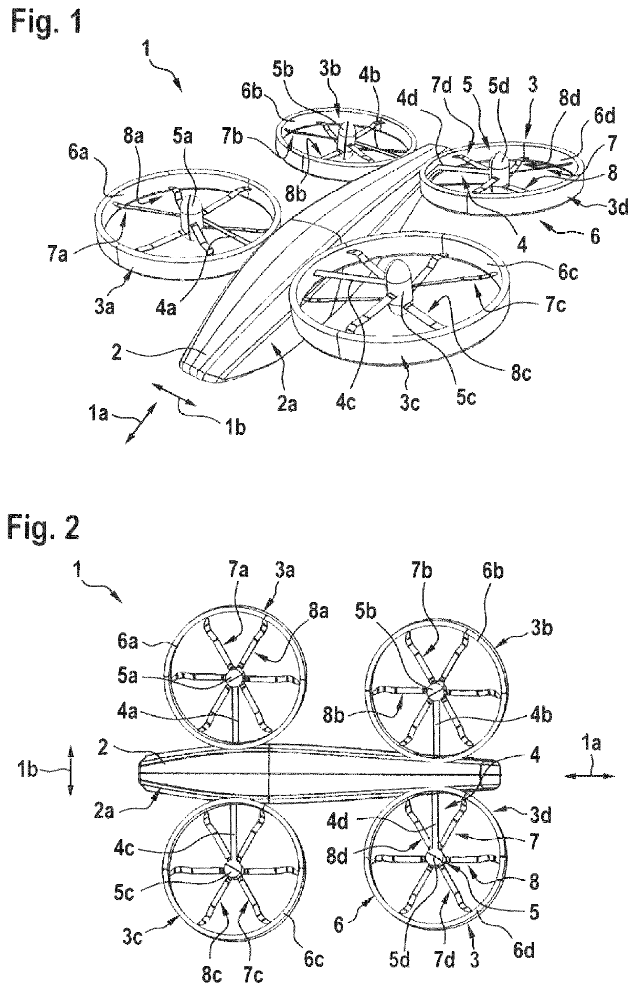
[0093]FIG. 1 shows a multirotor aircraft 1 with an aircraft airframe 2 according to the present invention. The aircraft airframe 2 defines a supporting structure that is also referred to hereinafter as the fuselage of the multirotor aircraft 1.
[0094]The fuselage 2 has a longitudinal length in longitudinal direction 1a and a transverse length in lateral direction 1b. The fore (illustrated at the left of FIG. 2) / aft (illustrated at the right of FIG. 2) locations of structures in the multirotor aircraft 1 are defined along the longitudinal direction 1a regarding a lateral plane.
[0095]The fuselage 2 also has an elevation length in elevation direction 1c (shown on FIG. 13). The upper / lower locations of structures in the multirotor aircraft 1 are defined along the elevation direction 1c regarding a longitudinal and transverse plane.
[0096]The fuselage 2 preferably defines an internal volume 2a that is at least adapted for transportation of passengers, so that the multirotor aircraft 1 as a...
PUM
Abstract
A multirotor aircraft with at least two thrust producing units, the multirotor aircraft being adapted for transportation of passengers and comprising an aircraft operating structure that is adapted for operation of the multirotor aircraft in failure-free operating mode, and a redundant security architecture that is at least adapted for operation of the multirotor aircraft in case of a failure of the aircraft operating structure in operation, the redundant security architecture being provided to comply with applicable authority regulations and certification requirements regarding passenger transportation.
Description
CROSS-REFERENCE TO RELATED APPLICATIONS[0001]This application is the U.S. National Phase of PCT Application No. PCT / EP2016 / 081574 filed Dec. 16, 2016, which claims priority to European Application No. EP 15400058.2 filed Dec. 21, 2015, the disclosures of which are incorporated in their entirety by reference.BACKGROUND OF THE INVENTION(1) Field of the Invention[0002]The invention is related to a multirotor aircraft with at least two thrust producing units, i.e. a rotorcraft having for instance four, six, ten or more thrust producing units.(2) Description of Related Art[0003]Various conventional multirotor aircrafts are known, e. g. from the documents EP2551190, EP2551193, EP2551198, EP2234883, WO2015028627, U.S. D678169, U.S. Pat. Nos. 6,568,630, 8,393,564, 7,857,253, 7,946,528, 8,733,690, US20070034738, US20130118856, DE102013108207, GB905911 and CN201306711. Other multirotor aircrafts are also known from the state of the art, such as e. g. the Boeing CH-47 tandem rotor helicopter, ...
Claims
Application Information
Patent Timeline
Application Date:The date an application was filed.
Publication Date:The date a patent or application was officially published.
First Publication Date:The earliest publication date of a patent with the same application number.
Issue Date:Publication date of the patent grant document.
PCT Entry Date:The Entry date of PCT National Phase.
Estimated Expiry Date:The statutory expiry date of a patent right according to the Patent Law, and it is the longest term of protection that the patent right can achieve without the termination of the patent right due to other reasons(Term extension factor has been taken into account ).
Invalid Date:Actual expiry date is based on effective date or publication date of legal transaction data of invalid patent.

