Waveguide phase shifter including a straight waveguide section and a curved waveguide section having vias that can be filled or emptied
- Summary
- Abstract
- Description
- Claims
- Application Information
AI Technical Summary
Benefits of technology
Problems solved by technology
Method used
Image

Examples
example 1
al Phase Shifter Using a Combination of Straight Waveguide and Curved Waveguide
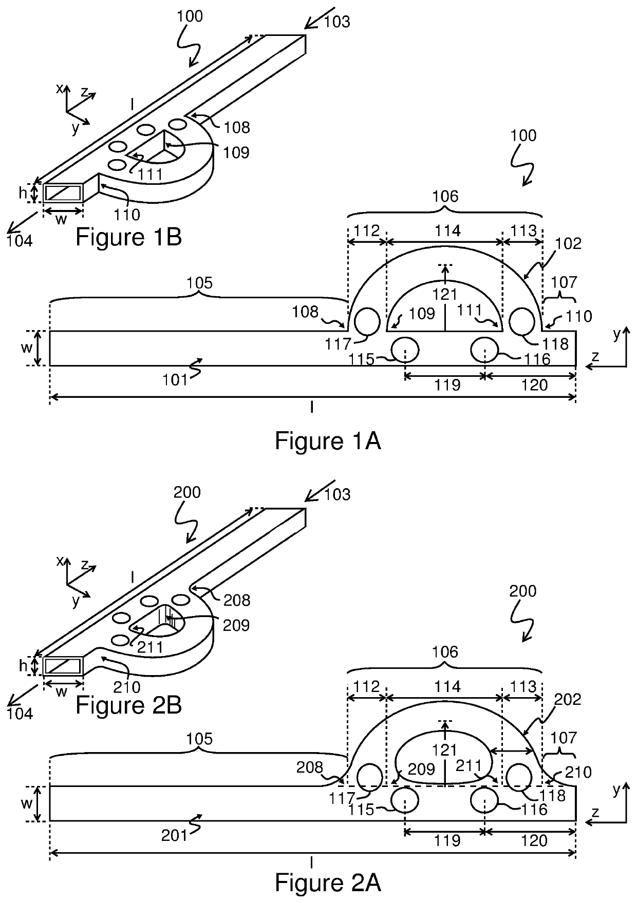
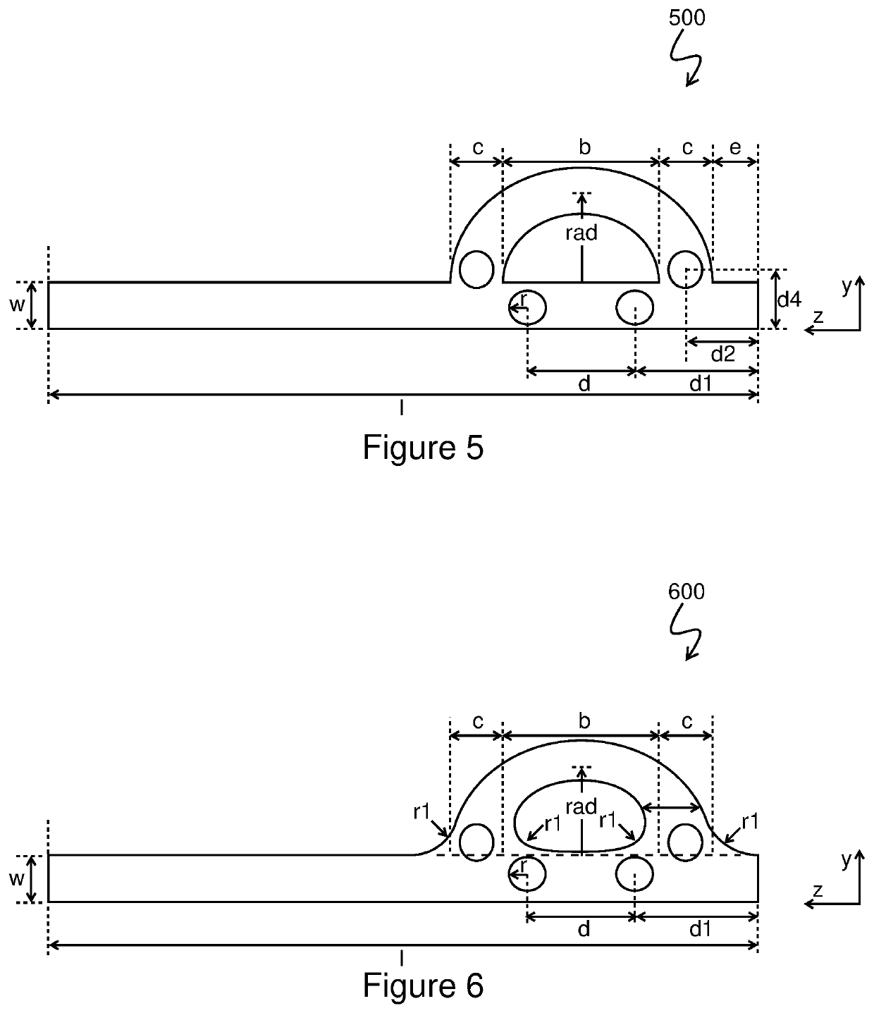
[0052]This example demonstrates step-wise phase shifts in increments of 90° and their multiples. FIG. 5 shows the configuration of the phase shifter 500 comprising a combination of straight and curved waveguide. The phase shifter 500 shares the same general features of phase shifter 100 (FIG. 1A, FIG. 1B). The y-direction and z-direction are labeled. For the phase shifter 500, l and w are the length and width of the straight waveguide, respectively as shown in FIGS. 5-8. Rad and c are the average radius and the width of the curved section, respectively, and r is the radius of a via. All of the vias had the same radius r. The height h (FIG. 1B) of the waveguide section is 1.5 mm. Other relevant dimensions to the example are shown in Table 1. All measures have units of millimeters (mm). By controlling the positions of the two vias using liquid metal, a differential phase close to 90° was achieved, as indica...
example 2
fter Bandwidth Using a Combination of Straight and Curved Waveguide Sections with Rounded Corners
[0055]This example shows configuration aspects which allow for wide band differential phase shifter. FIG. 6 shows a phase shifter 600 comprising a combination of straight and curved waveguide sections with general features corresponding to the phase shifter 200 (FIG. 2A, FIG. 2B). The y-direction and z-direction are labeled. The dimensions for the example are indicated in Table 3. The height h (FIG. 2B) is 1.5 mm. Example 2 included rounding of all corners between the straight and curved waveguides as shown in FIG. 6. The radius r1 of the rounded corner is 1.7 mm. The value of r1 was optimized to improve the S11 bandwidth, and then the radius rad was selected to achieve a predetermined differential phase desired.
[0056]As shown in Table 4, including the rounding of the corners where the straight and curved waveguide sections, the phase shifter 400 resulted in a phase shift of nearly 90° b...
example 3
fter Bandwidth Using a Combination of Straight and Curved Waveguide Sections with Chamfered Corners
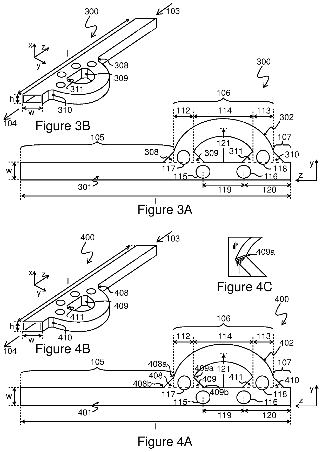
[0059]In this example phase shift is achieved with a phase shifter 700 as shown in FIG. 7. The y-direction and z-direction are labeled. This embodiment chamfers all corners between the straight and curved waveguides with general features corresponding to phase shifter 300 (FIG. 3A, FIG. 3B). The width of the chamfered corner is f and is equal to 1.7 mm and the angle 45° for all four corners.
[0060]Simulated results shown in Table 5 demonstrate that the bandwidth increases to 14.05 GHz by chamfering the corners but the phase shift was below 90 degrees which is often the most desired value. Besides the specific dimensions of the chamfer, the remaining dimensions are the same as given in Table 1 above.
[0061]
TABLE 5Differential phase after chamfering the cornersS11 S21S11S21Dif. ph.Dif. ph.Bandwidth(dB)(dB)(°)Δ = Q1 − Q2Δ = Q1 − Q2 + 360(GHz)Ref: straight−0.12−64.03Q1 = −155.69waveguiderad ...
PUM
 Abstract
Description
Claims
Application Information