
Telemetry method and system using an imager

Active Publication Date: 2021-08-10
THALES SA
View PDF9 Cites 0 Cited by
  • Summary
  • Abstract
  • Description
  • Claims
  • Application Information

AI Technical Summary

Benefits of technology

The invention is a device that uses an imager to measure the distance of a target. By using an imager instead of a photodiode and transimpedance circuit, the device becomes more sensitive and can align the laser emission more effectively. This increases the strength of the echo and improves the sensitivity of the detection. The device can also provide more accurate information about the target, allowing for fine pursuit. Additionally, the invention includes a computer program that allows for the same functionality.

Problems solved by technology

The increase in the flux of the emission is often limited by ocular safety constraints and the reduction in the divergence imposes high precision in the alignment of the emission on the target.
Despite the improvement in the distance measurement process by providing the best possible alignment over the most contributory part of the target through the spatial detection, the range is limited by the capacity of the temporal detection.

Method used


Image

  • Telemetry method and system using an imager
  • Telemetry method and system using an imager
  • Telemetry method and system using an imager

Examples


Embodiment Construction

[0053]From figure to figure, the same elements are tagged by the same references.

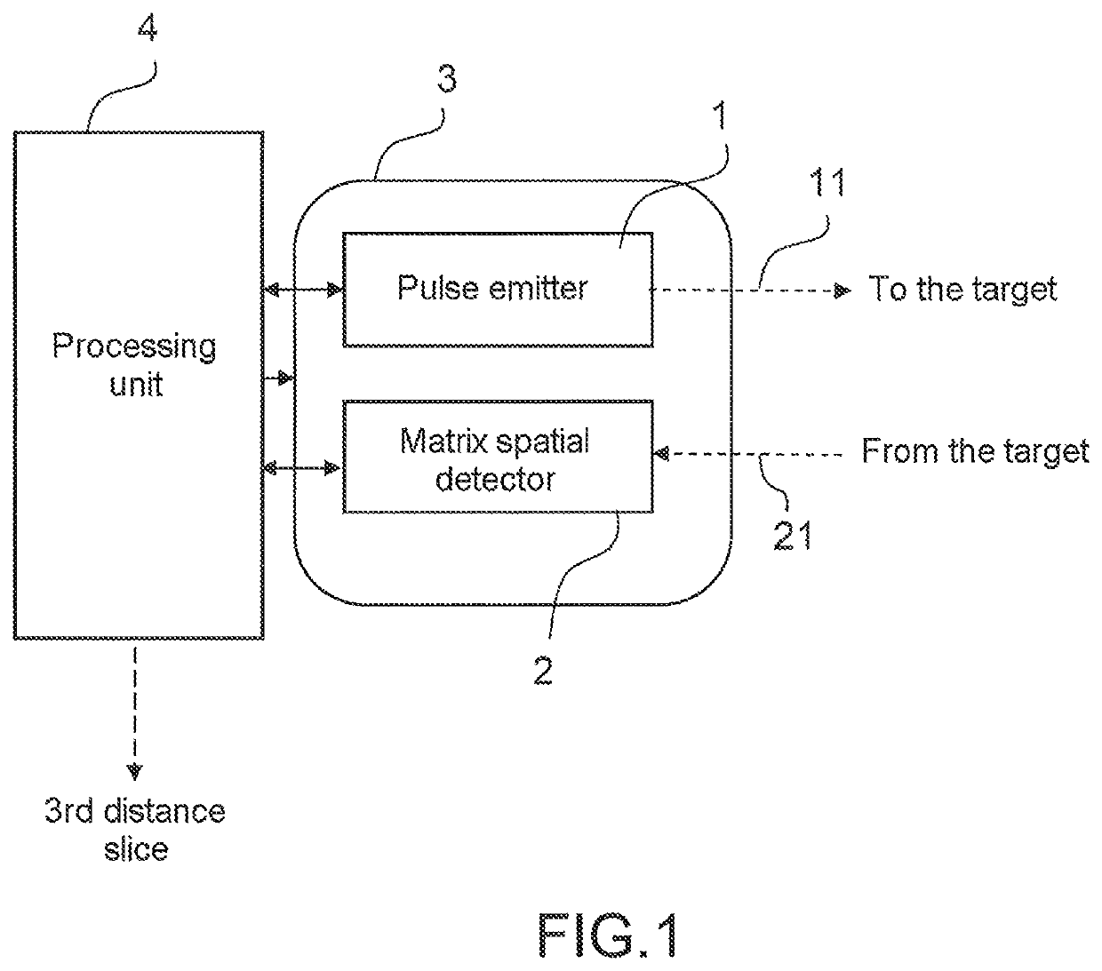
[0054]The distance measuring system according to the invention described in conjunction with FIG. 1, comprises:

[0055]an emitter 1 of laser pulses 11,

[0056]a matrix detector 2 (also referred to as imager) allowing the spatial detection of the image 21 of the target in passive mode and / or of the echoes 21 of the target in active mode,

[0057]a spectral filter placed in front of the receiver and centered on the wavelength of the laser so as to reduce the daytime optical flux and favor the detection of the echoes; it is optionally retractable,

[0058]means 3 for orienting the emitter and the receiver in the direction of a target to be telemetered; the angular field in which the target lies is for example of the order of a milliradian,

[0059]a processing unit 4 connected to the emitter, to the detector and to the orientation means and able to implement the method described hereinafter.

[0060]The present invention ...


PUM


Abstract

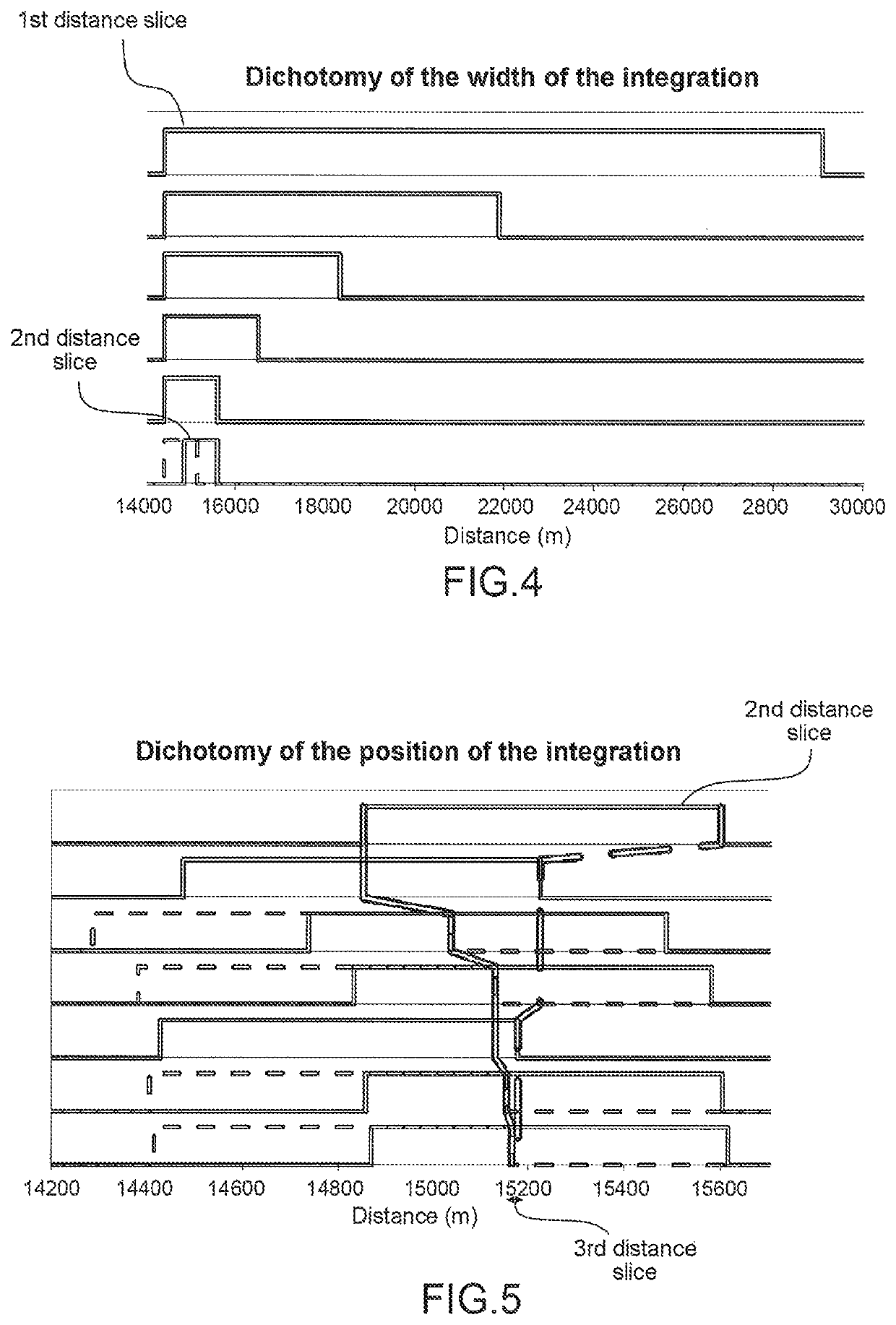
A method of measuring distance of a target by a pulse emitter and a matrix detector includes spatial mini-detectors coupled to capacitors whose duration of integration is controlled by a polarization of the mini-detectors. The method includes: A) determination of the direction of the target with respect to a known direction of the emitted pulses, and of a first integration period during which an echo of a pulse backscattered by the target is detected by the detector, determining a first distance slice in which the target is situated, B) reduction of the first distance slice in the course of successive telemetry iterations, that is to say emission of a pulse by the emitter and testing of detection of an echo by the detector, which are carried out: on the basis of the first integration period, by dichotomy of the duration of integration, and based on the detection of an echo of the target, a second distance slice in which the target is situated and included in the first distance slice, being determined on completion of this step, C) reduction of the second distance slice in the course of successive telemetry iterations which are carried out: on the basis of the integration period arising from step B, by variations of the position of the integration period, with constant durations of integration, and based on the detection of an echo of the target, a third distance slice in which the target is situated and included in the second distance slice, being determined on completion of this step.

Description

CROSS-REFERENCE TO RELATED APPLICATIONS[0001]This application is a National Stage of International patent application PCT / EP2016 / 079287, filed on Nov. 30, 2016, which claims priority to foreign French patent application No. FR 1502709, filed on Dec. 29, 2015, the disclosures of which are incorporated by reference in their entirety.FIELD OF THE INVENTION[0002]The field of the invention is that of the measurement of distance on the basis of the time for light to propagate between an object to be telemetered, called the target, and the system. The system emits light in the direction of the target. A fraction of the light emitted is backscattered toward the system. The system detects this light and estimates the distance on the basis of the return journey propagation time of the light. This telemetry principle has been used for a long time by laser pulsed telemeters.BACKGROUND[0003]These telemeters make it possible to measure the distances of non-cooperative targets with metric precisio...

Claims


Application Information

Patent Timeline
IPC IPC(8): G01C3/08G01S7/4863G01S7/481G01S17/42G01S7/499G01S17/10
CPCG01S7/4863G01S7/481G01S7/499G01S17/10G01S17/42
Inventor ROUSSEAU, PASCAL
Owner THALES SA
Learn More