
Monolithic MOS-SC circuit

A monolithic, switched capacitor circuit technology, applied in electrical pulse generator circuits, electrical components, electrical pulse generation, etc., to achieve the effects of low noise level, clock signal interference avoidance, and power demand reduction

Inactive Publication Date: 2003-01-22
EHNDRESS KHAUZER GMBKH KO KG +3
View PDF2 Cites 1 Cited by
  • Summary
  • Abstract
  • Description
  • Claims
  • Application Information

AI Technical Summary

Problems solved by technology

[0016] The present invention aims to solve these problems with respect to effectively reducing the tolerance range or margin to be considered in the design

Method used


Image

  • Monolithic MOS-SC circuit
  • Monolithic MOS-SC circuit
  • Monolithic MOS-SC circuit

Examples


Embodiment Construction

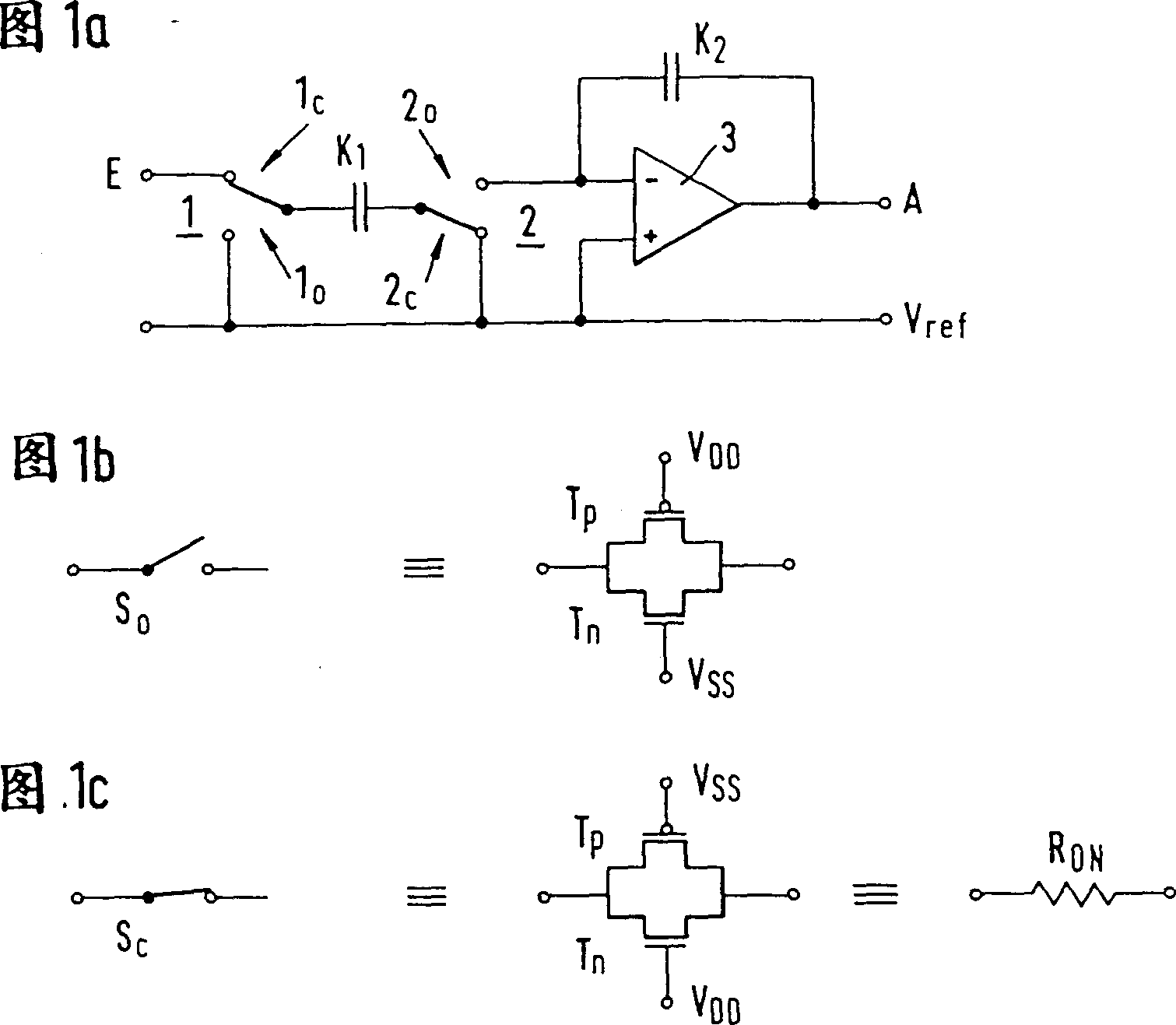
[0036] Figure 1a shows a circuit diagram of a simple SC circuit, which can be understood as the basic circuit of a general SC circuit on which switched capacitors are formed. An input E can be connected on the one hand to the first terminal of the first capacitor K1 via the first switching path 1c of the first changeover switch 1, and on the other hand can be connected to the ground reference potential Vref via the second switching path 1o, which can be, for example, The potential at the zero point of a circuit.

[0037] The second terminal of the first capacitor K1 can be connected to the inverting input terminal of an operational amplifier 3 through the first switch path 2o of the second transfer switch 2 on the one hand, and can be connected to the reference potential Vref through the second switch path 2c on the other hand. connected. The non-inverting input terminal of the operational amplifier 3 is connected to the reference potential Vref. An output terminal A of the ...


PUM


Abstract

With regard to a significant reduction in the tolerance range or margin to be taken into account in the design of a switched-capacitor circuit which is monolithically integrated by means of enhancement-mode insulated-gate field-effect transistors there is provided at least one opamp. This opamp contains a resistor which determines its quiescent current and is realized as a transistor operated in the permanently current-conducting state. An on-chip clock oscillator generates a clock signal. This oscillator is either an RC clock oscillator, whose frequency is determined by an oscillator resistor, which is realized as a transistor operated in the permanently current-conducting state, and an oscillator capacitor, or a current-controlled clock oscillator, whose frequency is determined by the quiescent current of the opamp. At least one capacitor is charged or discharged during operation by the opam via at least one switch in the form of a transistor clocked by the clock signal.

Description

technical field [0001] The present invention relates to monolithic switched capacitor circuits. Background technique [0002] The basic components of a monolithic switched capacitor circuit (MOS-SC) integrated with enhancement mode insulated gate field effect transistors are: [0003] - An operational amplifier, the corresponding quiescent current of which is determined by a resistor or by a current source which may be part of a current mirror. [0004] - an on-chip clock oscillator or RC clock oscillator for generating the clock signal, the frequency of which is determined by an oscillating resistor and an oscillating capacitor, [0005] - a plurality of capacitors located between the signal input terminal and the signal output terminal, and [0006] - Switches in the form of transistors via which the corresponding capacitor is charged or discharged clocked by a clock signal when the corresponding operational amplifier is in operation. [0007] In the case of MOS-SC circ...

Claims


Application Information

Patent Timeline
IPC IPC(8): H03K3/02H03H19/00
CPCH03H19/004
Inventor 皮特鲁斯·H·西辛克
Owner EHNDRESS KHAUZER GMBKH KO KG
Learn More