
Image-processing device, fluorescence observation device and method for emulating a first type of fluorescence observation device on a second type of fluorescence observation device

a fluorescence observation and image processing technology, applied in the field of image processing devices, fluorescence observation devices and methods, can solve the problems of difficulty for surgeons trained in the use of another fluorescence technology to safely handle the information provided by the new technology, and the inability to accept new technology by surgeons

Active Publication Date: 2021-08-10
LEICA INSTR SINGAPORE PTE
View PDF9 Cites 0 Cited by
  • Summary
  • Abstract
  • Description
  • Claims
  • Application Information

AI Technical Summary

Benefits of technology

[0011]For example, the image-processing device may be further configured to retrieve at least one digital white-light color image recorded by the second type of fluorescence observation device and representing the object illuminated by white light and to compute the digital emulated output image from a combination of the at least one digital fluorescence image to which the type-emulation module has been applied and the at least one digital white-light color image. In this embodiment, the combination of the digital white-light color image and the digital fluorescence image allows to put the fluorescing features of the object into context with non-fluorescing features which otherwise would be invisible in the digital fluorescence image.
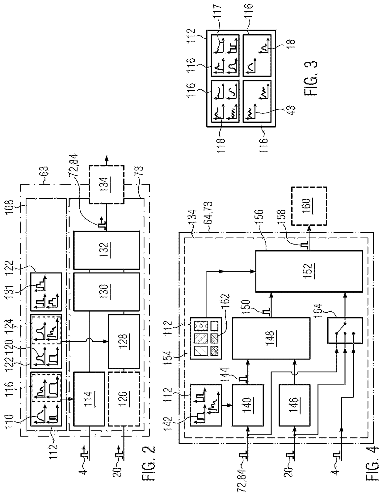
[0026]According to one advantageous embodiment, the type-emulation module may contain a digital background-emulation filter, which is representative of at least one of: an illumination spectrum of a light source of the first type of fluorescence observation device; an optical illumination filter located between the light source and an observation area of the first type of fluorescence observation device; and an optical recording filter located between a camera system of the first type of fluorescence observation device. The digital background-emulation filter allows the non-fluorescing background to be rendered in the digital emulated output image as it would have been rendered by the first type of fluorescence observation device.
[0036]The digital background-emulation filter may be computed by combining, e.g. multiplying in the spectral domain, at least two of the list containing at least one digital light-source filter, at least one digital illumination filter and at least one digital recording filter. The modular design of the digital background-emulation filter allows different types or setups of fluorescence observation devices to be easily emulated on the second type. The digital background-emulation filter, digital light-source filter, digital illumination filter and / or digital recording filter may be selectable by a user, for example via a graphical user interface of the second type of observation device. The user may thus put together the first type of fluorescence observation device that he or she wishes to emulate on the second type of observation device by selecting its digital representation on the second type of fluorescence observation device. The type-emulation module may also be selected from a library by the user via a graphical user interface in order to switch quickly between different types of fluorescence observation devices.

Problems solved by technology

When new fluorescence technologies are developed, it is often difficult for the surgeon trained in the use of another fluorescence technology to safely handle the information provided by the new technology.
The acceptance of new technology by surgeons may be impaired due to liability issues arising from a fear of being insufficiently acquainted with the new technology.

Method used


Image

  • Image-processing device, fluorescence observation device and method for emulating a first type of fluorescence observation device on a second type of fluorescence observation device
  • Image-processing device, fluorescence observation device and method for emulating a first type of fluorescence observation device on a second type of fluorescence observation device
  • Image-processing device, fluorescence observation device and method for emulating a first type of fluorescence observation device on a second type of fluorescence observation device

Examples


Embodiment Construction

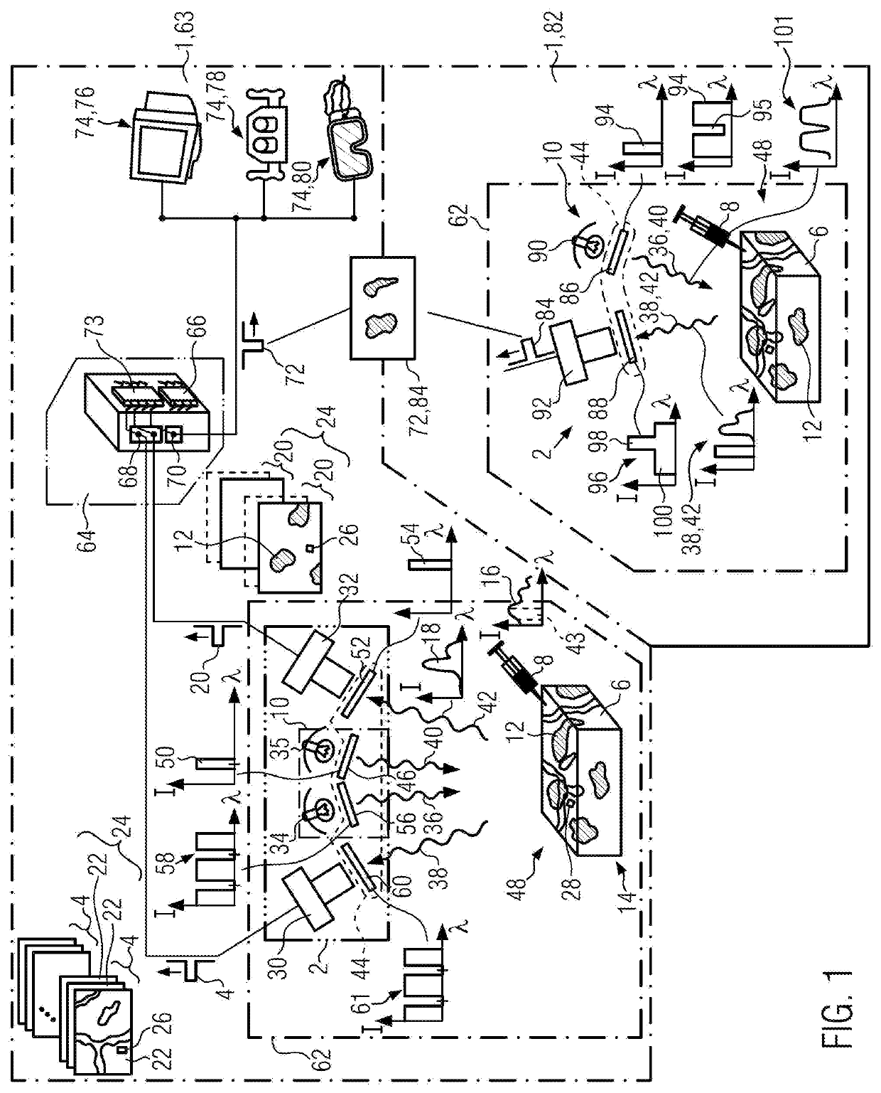
[0060]First, the structure and function of a fluorescence observation device 1 is described with reference to FIG. 1. For exemplary purposes, the fluorescence observation device 1 of FIG. 1 is a fluorescence microscope, in particular a fluorescence surgical microscope. It may alternatively be a fluorescence endoscope, in particular a surgical fluorescence microscope, to which the following description is also applicable.

[0061]The fluorescence microscope or endoscope 1 may comprise a camera system 2. The camera system 2 is configured to record at least one digital white-light color image 4 of an object 6, which may in particular be live tissue, such as live tissue of a patient undergoing surgery or a cell that is e.g. undergoing biopsy. The object 6 has been provided with one or more fluorophores 8 or otherwise contains one or more fluorophores 8. The camera system 2 may be stereoscopic or holographic. The resulting images may be recorded in a corresponding data format, i.e. a two-di...


PUM


Abstract

An image-processing device (64) for a fluorescence observation device (1), such as a microscope or endoscope, emulates a first type (82) of fluorescence display device on a second type (63) of fluorescence display device (1). Proficient use of a fluorescence observation device (1) for surgery requires years of training and experience. As technology quickly advances, new types of fluorescence observation devices provide different and more information than older types of fluorescence observation devices, however adoption of newer types is slow because new training is needed. The present disclosure facilitates the switch from one type of fluorescence observation device to another by providing a type-emulation module (108), which allows the imaging result obtained from the first type of fluorescence observation device to be emulated on the second type. The type-emulation module (108) is applied to a digital fluorescence image (20) in which the fluorescence of a fluorescing fluorophore (8) is recorded.

Description

CROSS REFERENCE TO RELATED APPLICATIONS[0001]This application claims priority of European patent application number 18215010.2 filed Dec. 21, 2018, the entire disclosure of which is incorporated by reference herein.FIELD OF THE INVENTION[0002]The invention relates to an image-processing device, to a fluorescence observation device comprising such an image-processing device and to a method for emulating a first type of fluorescence observation device on a second, different type of fluorescence observation device. The fluorescence observation device may in particular be a microscope or endoscope, in particular a fluorescence microscope or a fluorescence endoscope and more specifically a surgical fluorescence microscope or a surgical fluorescence endoscope.BACKGROUND OF THE INVENTION[0003]Fluorescence observation devices such as fluorescence microscopes and endoscopes greatly facilitate surgery and pathology. One or more fluorophores are injected into the object observed by the fluores...

Claims


Application Information

Patent Timeline
Patent Type & Authority Patents(United States)
IPC IPC(8): A61B1/04H04N9/76G02B21/00G02B21/16G02B21/36
CPCH04N9/76A61B1/043G02B21/0012G02B21/16G02B21/365A61B90/361A61B90/37A61B90/20A61B5/0071A61B1/06A61B1/05G02B5/20A61B2090/373G02B23/24A61B1/00004A61B1/00009A61B2090/371A61B2090/364A61B2090/365A61B90/30A61B2090/304A61B2090/372A61B2090/502G01N21/6458
Inventor THEMELIS, GEORGE
Owner LEICA INSTR SINGAPORE PTE
Learn More