Cae analysis method and cae analysis apparatus

a technology of cae and analysis method, applied in the field of cae (computer aided engineering) analysis technique, can solve the problems of increasing the number of model generating steps and too many model generating steps, and achieve the effect of simple structure, easy emulated and easy emulated

Inactive Publication Date: 2015-06-11
TOYOTA JIDOSHA KK
View PDF6 Cites 6 Cited by
  • Summary
  • Abstract
  • Description
  • Claims
  • Application Information

AI Technical Summary

Benefits of technology

[0009]The present invention is made in view of the above problems of the conventional art, and an object of the present invention is to make available a CAE analysis method and CAE analysis apparatus that can perform an appropriate modeling for a weld joint between a plurality of members in a simple manner, with a capability of representing moment transfer.
[0014]According to the first invention, each node of the shell element applied for the weld joint is allowed to have a rotational degree-of-freedom. Therefore, moment transfer via the weld joint can be appropriately represented. Further, a shape of the shell element applied as the model for the weld joint can be determined regardless of a mesh form formed by the solid elements applied for the members, whereby moment transfer can be represented with a simple structure. Thus, the CAE analysis method can be provided in which an appropriate modeling can be performed for a weld joint between a plurality of members in a simple manner, with representation of moment transfer enabled by the modeling.
[0015]According to the second invention, input to the welded portion and transmission of the input can be easily emulated so as to be approximated to an actual behavior.
[0016]According to the third invention, the CAE analysis apparatus can be provided in which an appropriate modeling can be performed for a weld joint between a plurality of members in a simple manner, with representation of moment transfer enabled by the modeling.
[0017]According to the fourth invention, input to the welded portion and transmission of the input can be easily emulated so as to be approximated to an actual behavior.

Problems solved by technology

However, such arrangement of the shell elements increases the number of model generating steps.
However, in this case, shapes of the solid elements of the bead of the arc welding are formed depending on a mesh form formed by the solid elements of the sheet metal portions, so that too many steps of model generating are required and modeling of the bead of the arc welding needs to be performed by using extremely small solid elements with a micro mesh pitch.

Method used


Image

  • Cae analysis method and cae analysis apparatus
  • Cae analysis method and cae analysis apparatus
  • Cae analysis method and cae analysis apparatus

Examples


Embodiment Construction

[0030]An embodiment of the present invention will be described below with reference to the drawings.

[0031]

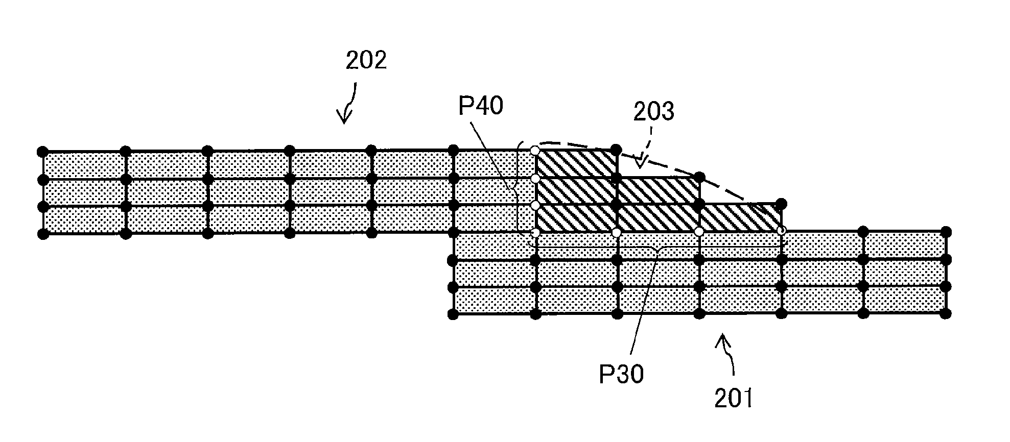
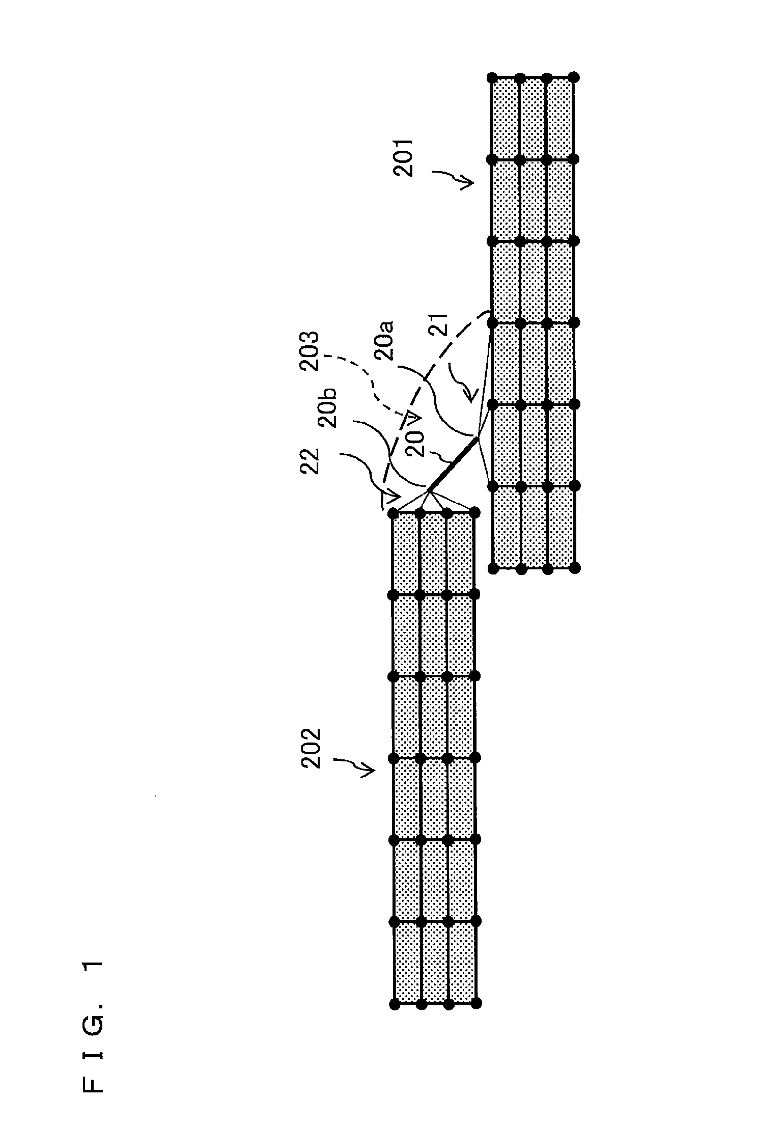
[0032]Firstly, a CAE analysis for a weld joint between sheet metals will be described with reference to FIGS. 10 to 12. For the CAE analysis described with reference FIGS. 10 to 12, a modeling technique in which solid elements and shell elements are used, and a modeling technique in which only solid elements are used, will be described.

[0033]FIG. 10 illustrates coupling under a contact definition in the case of modeling of sheet metal portions at the thickness center by shell elements. A shell element 103 that is a part of a shell element 101 representing an object (one of sheet metals), and a node 102a of a shell element 102 representing another object (the other of the sheet metals) are coupled to each other under the contact definition. It is assumed that the profiles of the shell elements 101 and 102 in FIG. 10 are repeated over a predetermined range in a direction perpendic...


PUM


Abstract

A CAE analysis method is provided in which a computer is caused to perform modeling in which: a model formed by solid elements is applied for each of the plurality of members, based on given data representing a region to be analyzed of the plurality of members;a model formed by a shell element is applied for each weld joint formed between two members of the plurality of members, based on given data representing a region to be analyzed of the weld joints; and the shell element applied as the model for each weld joint is arranged inside a dihedral between welded surfaces of the two members, and is coupled to the solid elements applied as the model for each of the two members through internode connection such that each solid elements applied for the two members is coupled via rigid elements or beam elements to the shell element respectively.

Description

BACKGROUND[0001]1. Field[0002]The present invention relates to a CAE (Computer Aided Engineering) analysis technique that causes a computer to perform modeling of an object to be analyzed, and analyze behavior of a model generated by the modeling.[0003]2. Description of the Related Art[0004]CAE analysis performed by a computer is widespread. In the CAE analysis, a computer converts a target object into CAD (Computer Aided Design) data, and performs modeling of the target object having been converted into the CAD data, to analyze strength of a structure, stress distribution, a material deformation characteristic, and the like by using an analysis method such as a finite element method. Also for vehicles, the CAE analysis is developed, and various calculations for engine structures, body structures, and the like are performed.[0005]Japanese Laid-Open Patent Publication No. 2012-112852 discloses that, in a structure where sheet metals are welded to each other, a weld joint is modeled b...

Claims


Application Information

Patent Timeline
Patent Type & Authority Applications(United States)
IPC IPC(8): G06F17/50
CPCG06F17/50G06F2113/24G06F2111/10G06F30/23G06F30/00
Inventor ARITA, KOSUKESUZUKI, MAISHINOHARA, KEIJI
Owner TOYOTA JIDOSHA KK
Why Eureka
Try Eureka