
Ultrasound apparatus and ultrasound emission method

a technology of ultrasonic equipment and emission method, which is applied in the direction of ultrasonic/sonic/infrasonic image/data processing, instruments, applications, etc., can solve the problems of inaccurate ultrasound detection, weak wave strength at the beginning and end of the ultrasound plane wave,

Active Publication Date: 2021-08-17
LELTEK INC
View PDF18 Cites 2 Cited by
  • Summary
  • Abstract
  • Description
  • Claims
  • Application Information

AI Technical Summary

Benefits of technology

[0013]According to the above description, in the ultrasound apparatus and the ultrasound emission method, through the operation of the switch module, the total number of the emitted ultrasound beams during a single scanning period is at least twice of the number of the transceiving channels. Thus, energy of the emission is increased, so the Signal-to-Noise Ratio (SNR) has been raised, such that the ultrasound detection is more precise and accurate, and the quality of the ultrasound image is also improved. Further, the total cycle time for a succeed scanning could be shortened, so as to lower the power consumption on ultrasound detection.

Problems solved by technology

However, when using the probe for ultrasound scanning, the wave strength at the beginning and the end of the ultrasound plane wave is usually weaker than the wave strength at the other parts of the ultrasound plane wave.
This usually leads to inaccurate ultrasound detection.

Method used


Image

  • Ultrasound apparatus and ultrasound emission method
  • Ultrasound apparatus and ultrasound emission method
  • Ultrasound apparatus and ultrasound emission method

Examples


Embodiment Construction

[0020]Reference will now be made in detail to the present preferred embodiments of the disclosure, examples of which are illustrated in the accompanying drawings. Wherever possible, the same reference numbers are used in the drawings and the description to refer to the same or like parts.

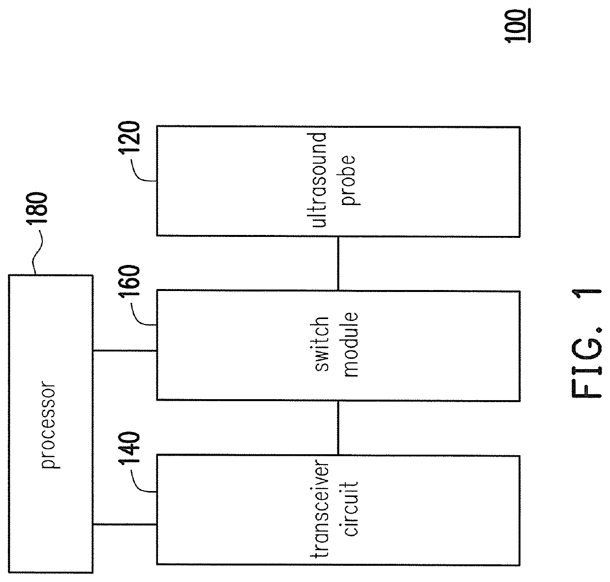
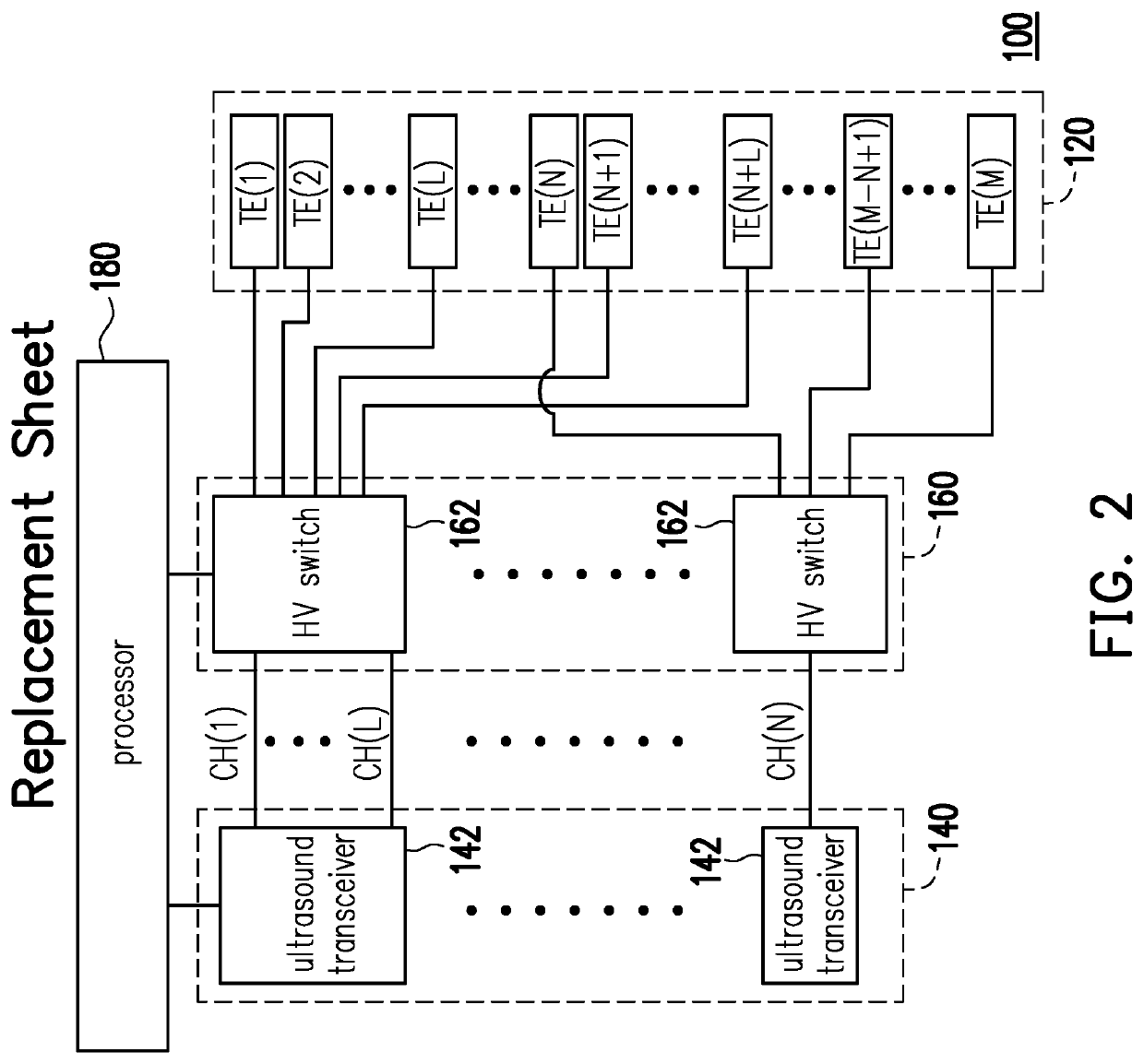
[0021]FIG. 1 is a block diagram illustrating an ultrasound apparatus according to an embodiment of the present disclosure. Referring to FIG. 1, in the present embodiment of the present disclosure, the ultrasound apparatus 100 includes an ultrasound probe 120, a transceiver circuit 140, a switch module 160 and a processor 180. The switch module 160 is switched between the ultrasound probe 120 and the transceiver circuit 140. The processor 180 is connected to the switch module 160 and the transceiver circuit 140, and thereby controls the switch module 160 and the transceiver circuit 140 for the ultrasound emission and detection. In an embodiment of the disclosure, the ultrasound apparatus 100 may be i...


PUM


Abstract

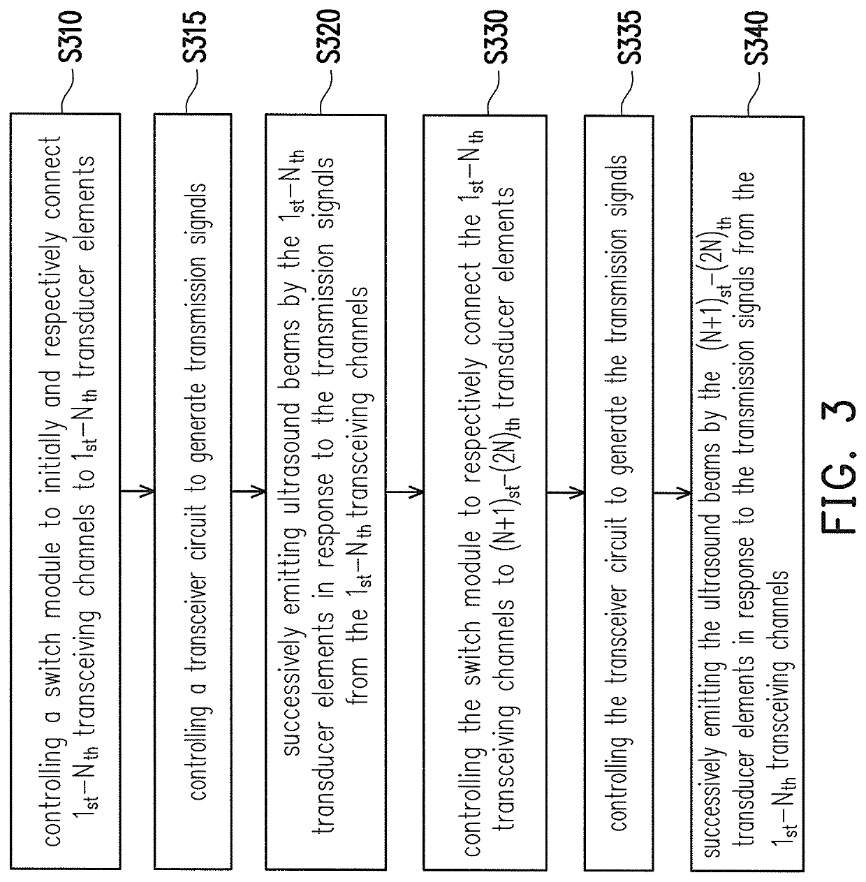
An ultrasound apparatus and a method of emitting plane wave are provided. The ultrasound apparatus includes an ultrasound probe, a transceiver circuit, a switch module and a processor. The ultrasound probe has a 1st to a Mth transducer elements for respectively emitting ultrasound beams to form the plane wave, and the transceiver circuit has a 1st to a Nth transceiving channels. M, N are positive integers, and M is a multiple of N. During a scanning period, the processor controls the switch module to initially and respectively connect the 1st-Nth transceiving channels to the 1st-Nth transducer elements, such that the 1st-Nth transducer elements successively emit the ultrasound beams. After the ultrasound beam is emitted by the Nth transducer element, the processor controls the switch module to respectively connect the 1st-Nth transceiving channels to the (N+1)th-(2N)th transducer elements, such that the (N+1)th-(2N)th transducer elements successively emit the ultrasound beams.

Description

BACKGROUNDTechnical Field[0001]The disclosure relates to an ultrasound apparatus and an ultrasound emission method adapted to the ultrasound apparatus.Description of Related Art[0002]Ultrasound has been widely used in medical diagnosis, military radar system and rusting detection. In the medical diagnosis system, the ultrasound is often used in imaging internal body structures such as tendons, muscles, joints, vessels and internal organs. Images obtained by the ultrasound may clearly show the internal body, which help medical personnel to correctly diagnose illness or disease of a patient. Thereafter, appropriate treatment could be chosen and performed to the patient.[0003]In a traditional medical ultrasound apparatus, during the ultrasound scanning of an object, ultrasound beams are outputted by a plurality of transducer elements in a probe to form a plane wave, and echoes of the plane wave are detected and recorded for generating the image of the internal structure of the object. ...

Claims


Application Information

Patent Timeline
Patent Type & Authority Patents(United States)
IPC IPC(8): A61B8/00A61B8/14G01S15/89A61B8/08
CPCA61B8/54A61B8/5207G01S15/89A61B8/145A61B8/4494G01S7/5202G01S15/8915
Inventor LIU, YING-YIPENG, SHENG-CHANGLIU, KUO-PING
Owner LELTEK INC
Learn More