Multiplexer, radio-frequency front-end circuit, and communication apparatus

a radio frequency front-end circuit and multi-channel technology, applied in the field of multi-channel, can solve the problems of demultiplexing characteristics and increase the insertion loss of the pass band, and achieve the effect of suppressing the increase in the insertion loss or degradation of the demultiplexing characteristic in ca mode, and suppressing the increase in the insertion loss or degradation of the demultiplexing characteristi

Active Publication Date: 2021-08-17
MURATA MFG CO LTD
View PDF13 Cites 0 Cited by
  • Summary
  • Abstract
  • Description
  • Claims
  • Application Information

AI Technical Summary

Benefits of technology

[0011]According to the above configuration, in accordance with one of connection and disconnection of the first switching element, at least one of the pass band and the attenuation band of the first filter is changeable. Thus, for example, (1) in a case where the frequency interval between two concurrently used frequency bands is small, the pass band of the first filter is made closer to the pass band of the second filter. This can suppress increase in insertion loss on the pass band side of the second filter in the pass band of the first filter. In addition, in accordance with the other of connection and disconnection of the first switching element, for example, (2) in a case where the frequency interval between two concurrently used frequency bands is large, the attenuation band of the first filter, located between the pass band of the first filter and the pass band of the second filter, is made closer to the pass band of the first filter. This can increase the isolation between the first filter and the second filter.
[0036]According to the present disclosure, it is possible to provide a multiplexer, a radio-frequency front-end circuit, and a communication apparatus in which increase in insertion loss or degradation of demultiplexing characteristics in CA mode is suppressed.

Problems solved by technology

Depending on the frequency interval or the boundary band, this increases the insertion loss of the pass band in at least one of the two frequency bands or degrades demultiplexing characteristics.

Method used


Image

  • Multiplexer, radio-frequency front-end circuit, and communication apparatus
  • Multiplexer, radio-frequency front-end circuit, and communication apparatus
  • Multiplexer, radio-frequency front-end circuit, and communication apparatus

Examples


first embodiment

[0069][1.1 Configuration of Communication Apparatus]

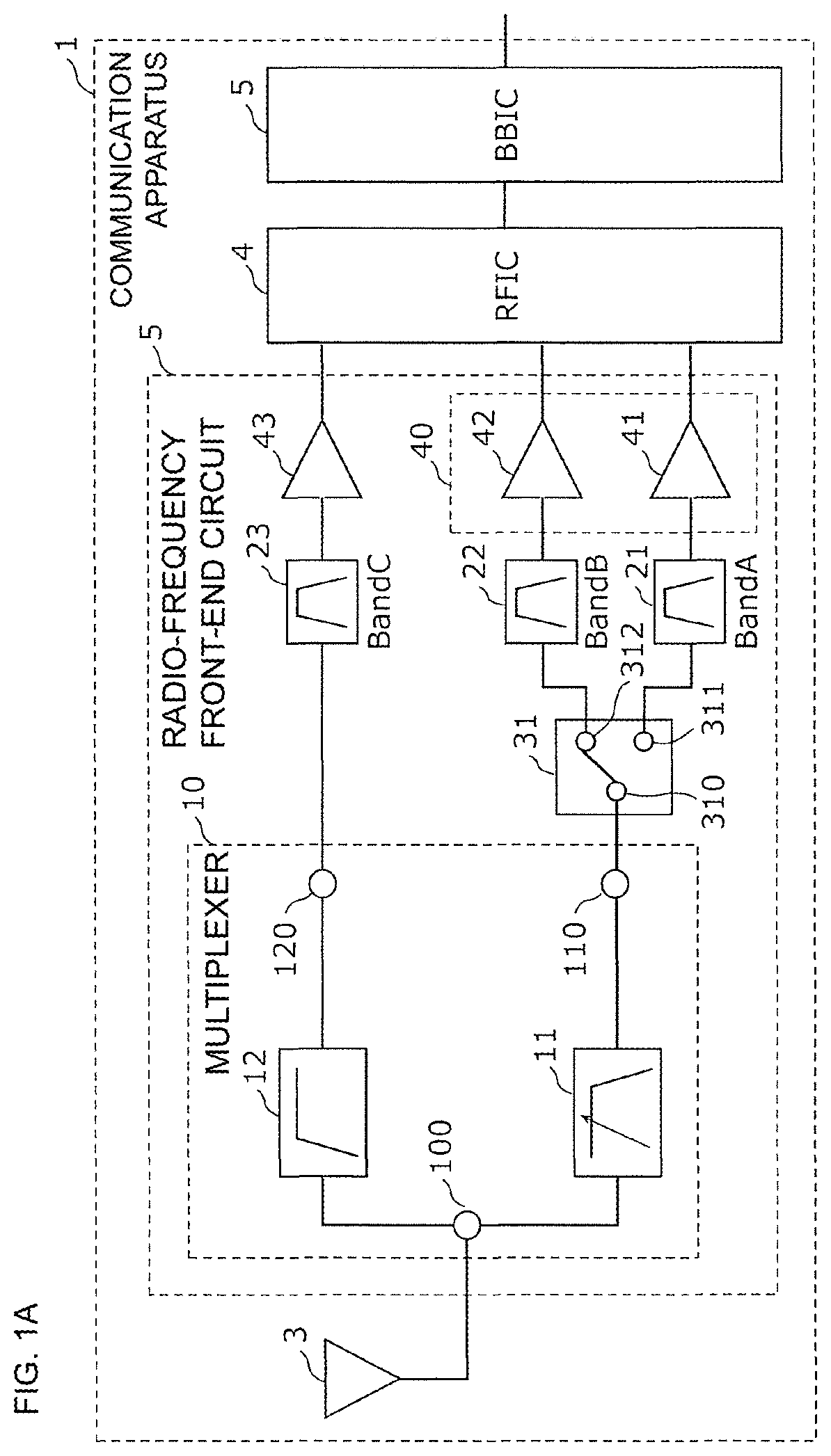
[0070]FIG. 1A illustrates a circuit configuration of a communication apparatus 1 according to a first embodiment. As illustrated in FIG. 1A, the communication apparatus 1 includes an antenna element 3, a radio-frequency front-end circuit 50, an RF signal processing circuit (RFIC) 4, and a baseband signal processing circuit (BBIC) 5.

[0071]The RFIC 4 is an RF signal processing circuit that processes radio-frequency signals transmitted and received by the antenna element 3. Specifically, the RFIC 4 performs signal processing on a radio-frequency signal (herein, radio-frequency reception signal) that is input from the antenna element 3 via the radio-frequency front-end circuit 50 by, for example, down-converting the radio-frequency signal, and outputs a reception signal generated by the signal processing to the BBIC 5. In addition, the RFIC 4 may perform signal processing on a transmission signal that is input from the BBIC 5 by, for e...

second embodiment

[0248]In the first embodiment, one of the plurality of filters constituting the multiplexer is a frequency-variable filter. In contrast, a multiplexer according to this embodiment has a configuration in which two of a plurality of filters constituting the multiplexer are frequency-variable filters.

[0249][2.1 Configuration of Radio-Frequency Front-End Circuit]

[0250]FIG. 12 illustrates a configuration of a radio-frequency front-end circuit 50L according to the second embodiment. As illustrated in the drawing, the radio-frequency front-end circuit 50L is a front-end circuit for reception and includes a multiplexer 10L, switches 31L and 32L, filters 21L, 22L, 23L, 24L and 25L, and reception amplifiers 41L, 42L, 43L, 44L, and 45L.

[0251]The multiplexer 10L includes the common terminal 100, the input / output terminals 110 and 120, a low-pass filter 11L, and a high-pass filter 12L.

[0252]The low-pass filter 11L is disposed between the common terminal 100 and the input / output terminal 110. The...


PUM


Abstract

A multiplexer capable of concurrently sending a radio-frequency signal in one of Band A and Band B belong to a low band group and a radio-frequency signal in a Band C belongs to a high band group that includes: a common terminal and input / output terminals; a low-pass filter arranged between the common terminal and the input / output terminal and whose pass band is frequencies in the low band group and whose attenuation band is frequencies in the high band group; and a high-pass filter arranged between the common terminal and the input / output terminal and whose pass band is the frequencies in the high band group and whose attenuation band is the frequencies in the low band group. The low-pass filter includes a first frequency-variable circuit including a switch, and at least one of the pass band and the attenuation band of the low-pass filter is changeable.

Description

[0001]This is a continuation of International Application No. PCT / JP2018 / 037881 filed on Oct. 11, 2018 which claims priority from Japanese Patent Application No. 2017-205195 filed on Oct. 24, 2017. The contents of these applications are incorporated herein by reference in their entireties.BACKGROUNDTechnical Field[0002]The present disclosure relates to a multiplexer, a radio-frequency front-end circuit, and a communication apparatus.[0003]In recent years, mobile communication terminals are required to support a plurality of frequency bands, or so-called multiband, with a single terminal, and also a front-end circuit arranged between an antenna element and an amplifier is required to support multiband. Along with this, in order to maintain the signal quality in each frequency band, a diplexer is arranged between an antenna element and a filter supporting each frequency band in the front-end circuit.[0004]Patent Document 1 discloses a circuit configuration of a diplexer including a lo...

Claims


Application Information

Patent Timeline
Patent Type & Authority Patents(United States)
IPC IPC(8): H04B1/00H03H7/46H03H9/72H04B1/18H04B1/40
CPCH04B1/0057H03H7/463H03H9/725H04B1/18H04B1/40H03H7/0115H03H7/1758H03H7/1766H03H2210/036H04B1/0458
Inventor HISANO, TAIZOTSUKAMOTO, HIDEKIMORI, HIROTSUGU
Owner MURATA MFG CO LTD
Why Eureka
Try Eureka