Medical image diagnostic device and image processing method

a diagnostic device and image processing technology, applied in the field of medical image diagnostic devices, can solve the problems of insufficient scan range set with the protocol in many cases, inaccuracy, and limitation of actual image sensing planning utilizing guidelines and protocols, and achieve the effect of improving operator labor and inaccuracy

Active Publication Date: 2021-08-24
FUJIFILM HEALTHCARE CORP
View PDF11 Cites 2 Cited by
  • Summary
  • Abstract
  • Description
  • Claims
  • Application Information

AI Technical Summary

Benefits of technology

[0012]According to the present invention, it is possible to improve the operator's labor and inaccuracy upon scan range setting, in correspondence with scan range reference which differs by hospital or operator.

Problems solved by technology

However, there is a limit to the actual image sensing planning utilizing the guidelines and the protocol.
Particularly, in the setting of the above-described scan range, as the positioning image differs by patient, the scan range set with the protocol is inappropriate in many cases.
Accordingly, in most cases, upon inspection, it is necessary for the operator to manually set the scan range, and inaccuracy occurs in the scan range setting.

Method used


Image

  • Medical image diagnostic device and image processing method
  • Medical image diagnostic device and image processing method
  • Medical image diagnostic device and image processing method

Examples


example 1

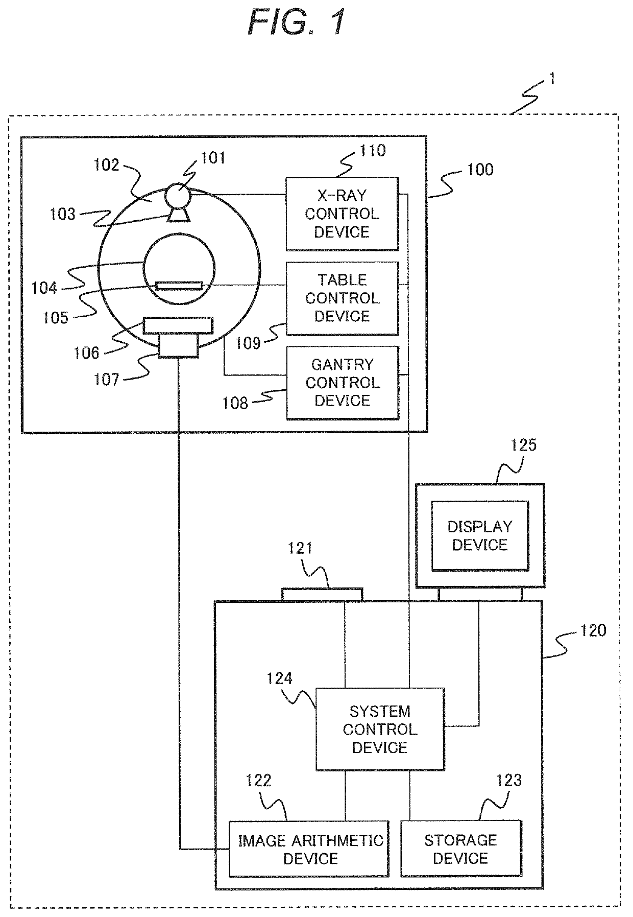
[0039]First, an example of the entire configuration of an X-ray CT apparatus to which the respective examples are applied will be described by using FIG. 1.

[0040]An X-ray CT apparatus 1 is provided with a scan gantry part 100 and a console 120. The scan gantry part 100 is provided with an X-ray tube 101, a rotary disc 102, a collimator 103, an X-ray detector 106, a data collection device 107, a table 105, a gantry control device 108, a table control device 109, and an X-ray control device 110.

[0041]The X-ray tube 101 is a device to irradiate a patient placed on the table 105 with an X-ray. The collimator 103 is a device to limit a radiation range of the X-ray irradiated from the X-ray tube 101. The rotary disc 102 is provided with an opening 104 which the patient placed on the table 105 enters. The rotary disc 102 is also provided with the X-ray tube 101 and an X-ray detector 106, and rotates around the patient. The X-ray detector 106 is a device oppositely provided to the X-ray tub...

example 2

[0072]Next, Example 2 will be described by using FIG. 9 to FIG. 11. In Example 2, in addition to automatic scan range setting as in the case of Example 1, an example in consideration of the influence of the height of the table on which the patient is set, will be described. That is, it is an example configured such that a map in which heights of the table on which the patient is placed and image magnification of positioning image are made to correspond to each other is stored in the storage part, and the scan range automatic setting unit refers to the map, and in correspondence with table height upon inspection, adjusts the margin values stored in the range setting pattern, to set the scan range.

[0073]Upon instruction, the table on which the patient is placed is moved mainly in the body axis direction and a body width direction, to be set in a position where the image sensing target can be image-sensed. In some cases, the table height is adjusted. As shown in FIGS. 9(a), (b) and (c)...

example 3

[0081]Next, Example 3 will be described by using FIG. 12 and FIG. 13. The present example is an example configured such that a map in which electrocardiographic waveforms of the patient and movements of the heart are made to correspond to each other is stored in the storage part, and the scan range automatic setting unit refers to the map based on the electrocardiographic waveform of the patient obtained upon image sensing of the positioning image, adjusts the margin value stored in the range setting pattern, and sets the scan range.

[0082]Among the body parts to be inspection targets include a part which always moves and a part which almost does not move, or does not move at all. When the inspection target is an organ which always moves, the position and the size of the organ may differ from those upon positioning-image image sensing. When the inspection target moves out of the set scan range during actual image sensing, an image necessary for diagnosis is not obtained. Accordingly,...


PUM


Abstract

With regard to a setting reference for X-ray irradiation range and image generation range, which differs by hospital or technician, a structure to automatically set a desired X-ray irradiation range and an image generation range infallibly, is provided. In an X-ray CT apparatus, a scan range automatic setting unit extracts an inspection target as an arbitrary body part designated by an operator before inspection from a positioning image, and generates an extraction region range including it. The operator sets an arbitrary margin value by line operation or numerical input using a GUI with respect to the extraction region range (S104). The scan range automatic setting unit generates and stores a range setting pattern in which the inspection target and the margin value are made to correspond to each other (S105), and links the range setting pattern to an inspection protocol (S106). Then immediately after positioning-image image sensing (S109), the scan range automatic setting unit extracts the inspection target from the positioning image (S112), and automatically sets a scan range, in accordance with the range setting pattern made to correspond to the inspection target and linked to the inspection protocol (S114).

Description

TECHNICAL FIELD[0001]The present invention relates to a medical image diagnostic device, and more particularly, to a technique of setting an X-ray irradiation range and an image generation range in actual image sensing using a positioning image obtained before actual image sensing.BACKGROUND ART[0002]Medical image diagnostic devices are essential for modern medicine, and as one of these devices, an X-ray CT (Computed Tomography) apparatus is known. The X-ray CT apparatus reconstructs a tomographic image of a patient with projection data from plural angles, obtained by circulating an X-ray source to irradiate the patient with an X-ray and an X-ray detector to detect the exposure dose of the X-ray transmitted through the patient, around the patient, and displays the reconstructed tomographic image. The image displayed with the X-ray CT apparatus describes the shapes of organs in the patient. The image is used in medical image diagnosis. As other medical image diagnostic devices, an MR...

Claims


Application Information

Patent Timeline
Patent Type & Authority Patents(United States)
IPC IPC(8): G06T7/00A61B6/00A61B6/03A61B6/04
CPCA61B6/545A61B6/032A61B6/0407A61B6/40A61B6/42A61B6/465A61B6/467A61B6/503A61B6/4435A61B6/469A61B6/541A61B6/544
Inventor TAKEMOTO, KAZUMA
Owner FUJIFILM HEALTHCARE CORP
Why Eureka
Try Eureka