
Ablation power control based on contact force

a technology of power control and contact force, applied in the field of tissue ablation systems, can solve the problems of unreliable binary contact indication, asynchronous rhythm, and disruption of normal cardiac cycle, and achieve the effect of increasing the predicted lesion siz

Active Publication Date: 2021-08-24
BIOSENSE WEBSTER (ISRAEL) LTD
View PDF25 Cites 1 Cited by
  • Summary
  • Abstract
  • Description
  • Claims
  • Application Information

AI Technical Summary

Benefits of technology

The patent describes a method and apparatus for ablation that predicts the size of the lesion created during a treatment. The method involves choosing a contact force between the ablation electrode and the target tissue, setting a power level, and setting a time interval. The method then predicts the lesion size using a non-linear function of the contact force, power level, and time interval. The predictions are made by iterating and saturation points are found until the desired size is reached. The method can also involve displaying the predictions while varying the contact force, power level, or time interval. The apparatus includes the ability to make the predictions and display them during the ablation treatment.

Problems solved by technology

Cardiac arrhythmias, such as atrial fibrillation, occur when regions of cardiac tissue abnormally conduct electric signals to adjacent tissue, thereby disrupting the normal cardiac cycle and causing asynchronous rhythm.
This sort of binary contact indication may be unreliable, however, and is sensitive to changes in the impedance between the body-surface electrode and the skin.

Method used


Image

  • Ablation power control based on contact force
  • Ablation power control based on contact force
  • Ablation power control based on contact force

Examples


Embodiment Construction

[0027]In the following description, numerous specific details are set forth in order to provide a thorough understanding of the various principles of the present invention. It will be apparent to one skilled in the art, however, that not all these details are necessarily always needed for practicing the present invention. In this instance, well-known circuits, control logic, and the details of computer program instructions for conventional algorithms and processes have not been shown in detail in order not to obscure the general concepts unnecessarily.

[0028]Aspects of the present invention may be embodied in software programming code, which is typically maintained in permanent storage, such as a computer readable medium. In a client / server environment, such software programming code may be stored on a client or a server. The software programming code may be embodied on any of a variety of known non-transitory media for use with a data processing system, such as a diskette, hard driv...


PUM


Abstract

Methods and systems are adapted for ablation of target tissue in a living subject by predicting a lesion size that would result from placing an ablation electrode into contact with the target tissue at a particular contact force while applying energy at a given power level for a particular time interval. The prediction involves modeling the lesion size as a non-linear function of the contact force, the power level and the time interval. The prediction may be iterated by varying the contact force, the power level or the time interval until a saturation point is found, beyond which the lesion size does not increase. After it is established that one of the iterations predicts a desired lesion size, ablation of the target tissue may be conducted using the contact force, the power level and the time interval of the one iteration.

Description

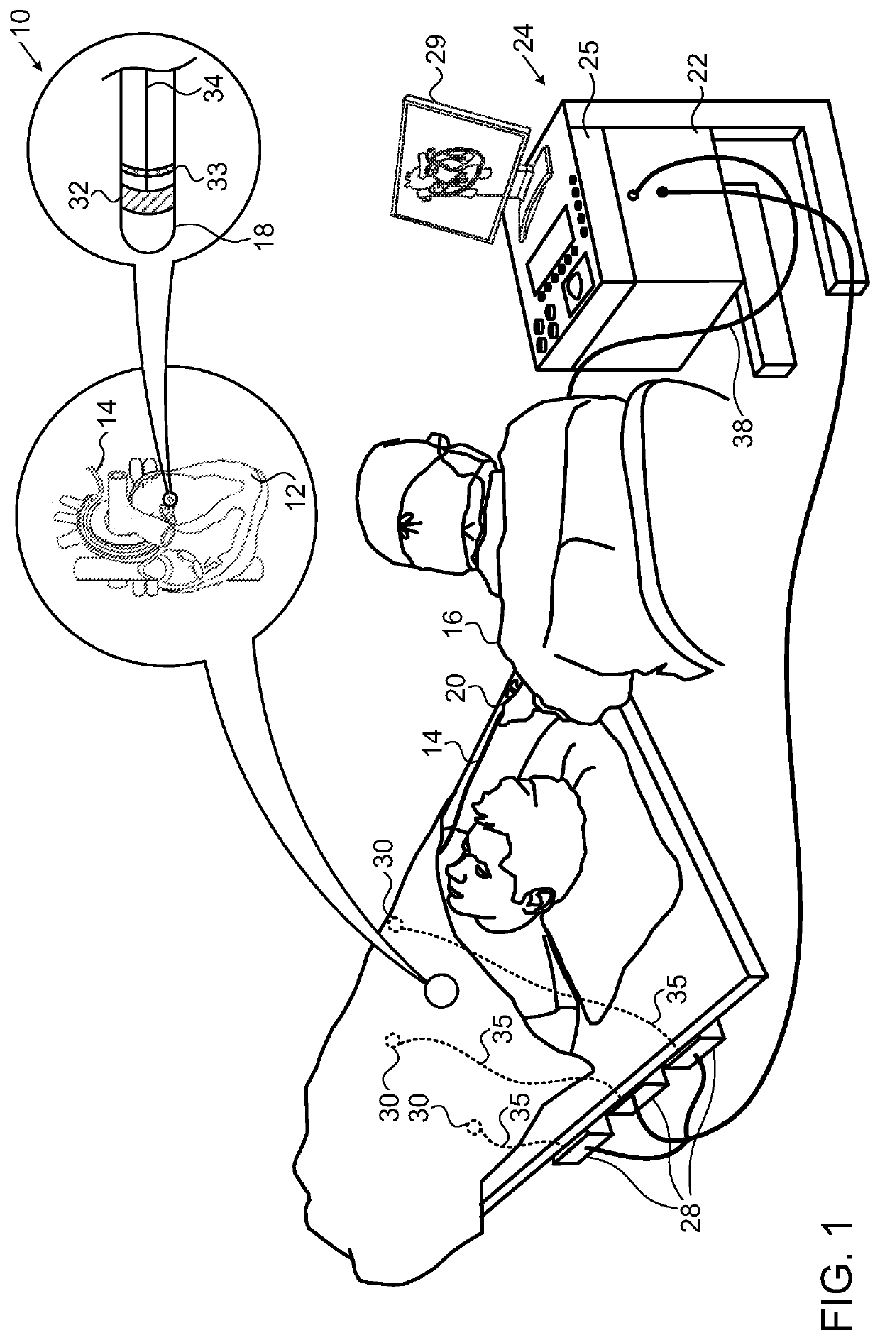
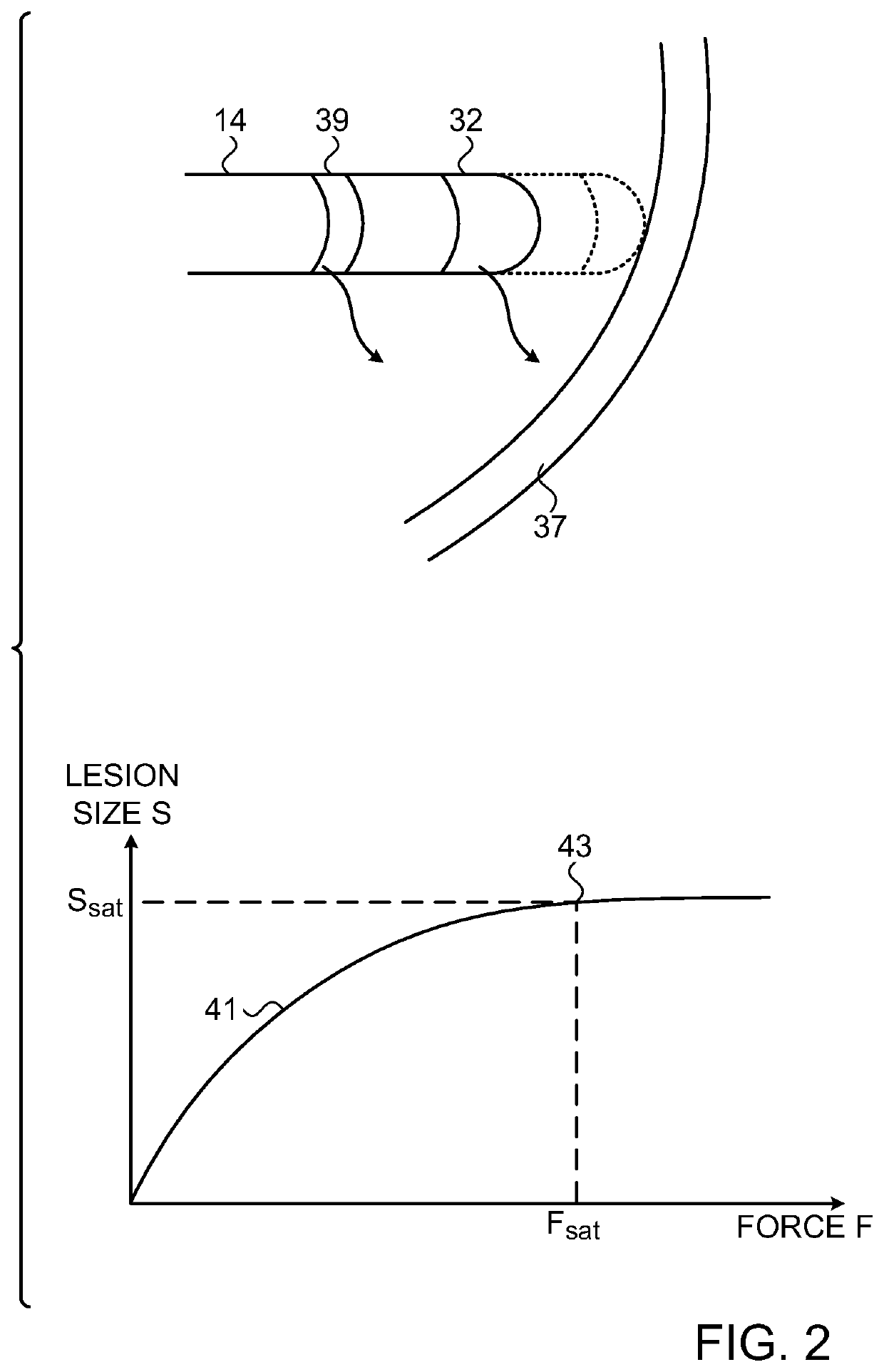
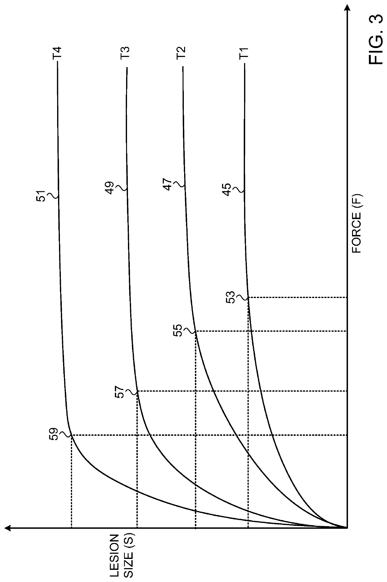
BACKGROUND OF THE INVENTION1. Field of the Invention[0001]This invention relates to tissue ablation systems. More particularly, this invention relates to monitoring of contact between an invasive probe and tissue within the body.2. Description of the Related Art[0002]Cardiac arrhythmias, such as atrial fibrillation, occur when regions of cardiac tissue abnormally conduct electric signals to adjacent tissue, thereby disrupting the normal cardiac cycle and causing asynchronous rhythm.[0003]Procedures for treating arrhythmia include surgically disrupting the origin of the signals causing the arrhythmia, as well as disrupting the conducting pathway for such signals. By selectively ablating cardiac tissue by application of energy via a catheter, it is sometimes possible to cease or modify the propagation of unwanted electrical signals from one portion of the heart to another. The ablation process destroys the unwanted electrical pathways by formation of non-conducting lesions.[0004]Verif...

Claims


Application Information

Patent Timeline
Patent Type & Authority Patents(United States)
IPC IPC(8): A61B18/00A61B18/14A61B34/10A61B90/00A61B34/20
CPCA61B18/1492A61B34/10A61B2018/00357A61B2018/00577A61B2018/00648A61B2018/00696A61B2018/00702A61B2018/00738A61B2018/00761A61B2018/00839A61B2034/104A61B2034/2051A61B2090/065A61B2018/00815A61B2018/00821A61B2034/2059A61B18/00
Inventor GOVARI, ASSAFPAPAIOANNOU, ATHANASSIOS
Owner BIOSENSE WEBSTER (ISRAEL) LTD
Learn More