Ultrasound generating method, apparatus and probe

a technology of ultrasound ablation and generator, which is applied in the field of high intensity ultrasound ablation apparatus and probe, can solve the problems of limiting the size and shape of the scar that can be produced, the inability of the physician to geometrically focus the ultrasound to a target, and the coagulation necrosis of the target tissu

Inactive Publication Date: 2006-10-26
KONINKLIJKE PHILIPS ELECTRONICS NV +1
View PDF7 Cites 100 Cited by
  • Summary
  • Abstract
  • Description
  • Claims
  • Application Information

AI Technical Summary

Problems solved by technology

Absorption of high intensity ultrasound in a focal region causes a significant temperature rise, resulting in coagulative necrosis of the target tissue.
In certain applications, geometrical focusing of ultrasound to a target is not possible.
While current ablation devices and methods produce an ablation pattern which is primarily device dependent, in complex anatomy, an ablation ...

Method used


Image

  • Ultrasound generating method, apparatus and probe
  • Ultrasound generating method, apparatus and probe
  • Ultrasound generating method, apparatus and probe

Examples


Embodiment Construction

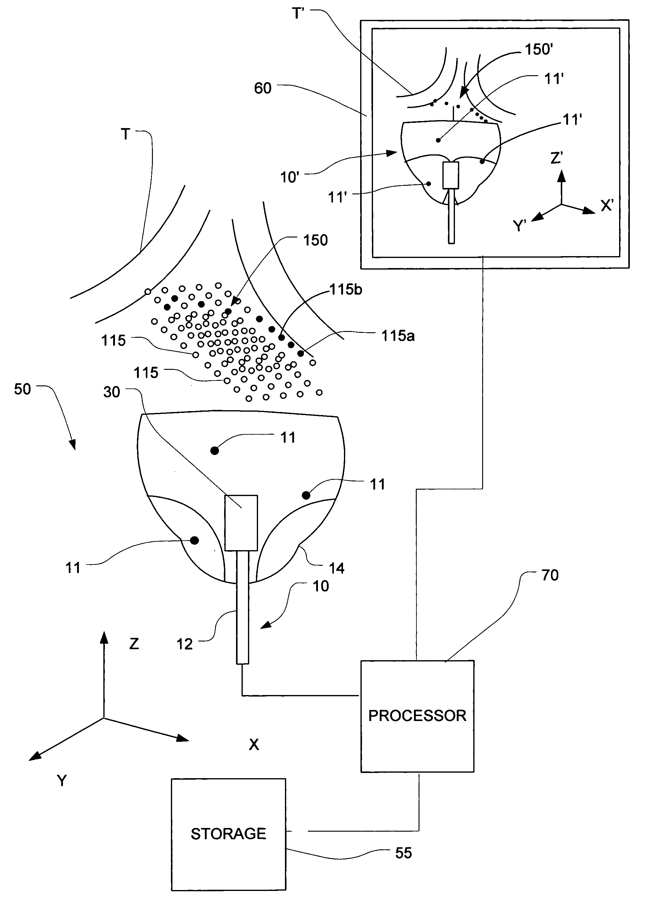
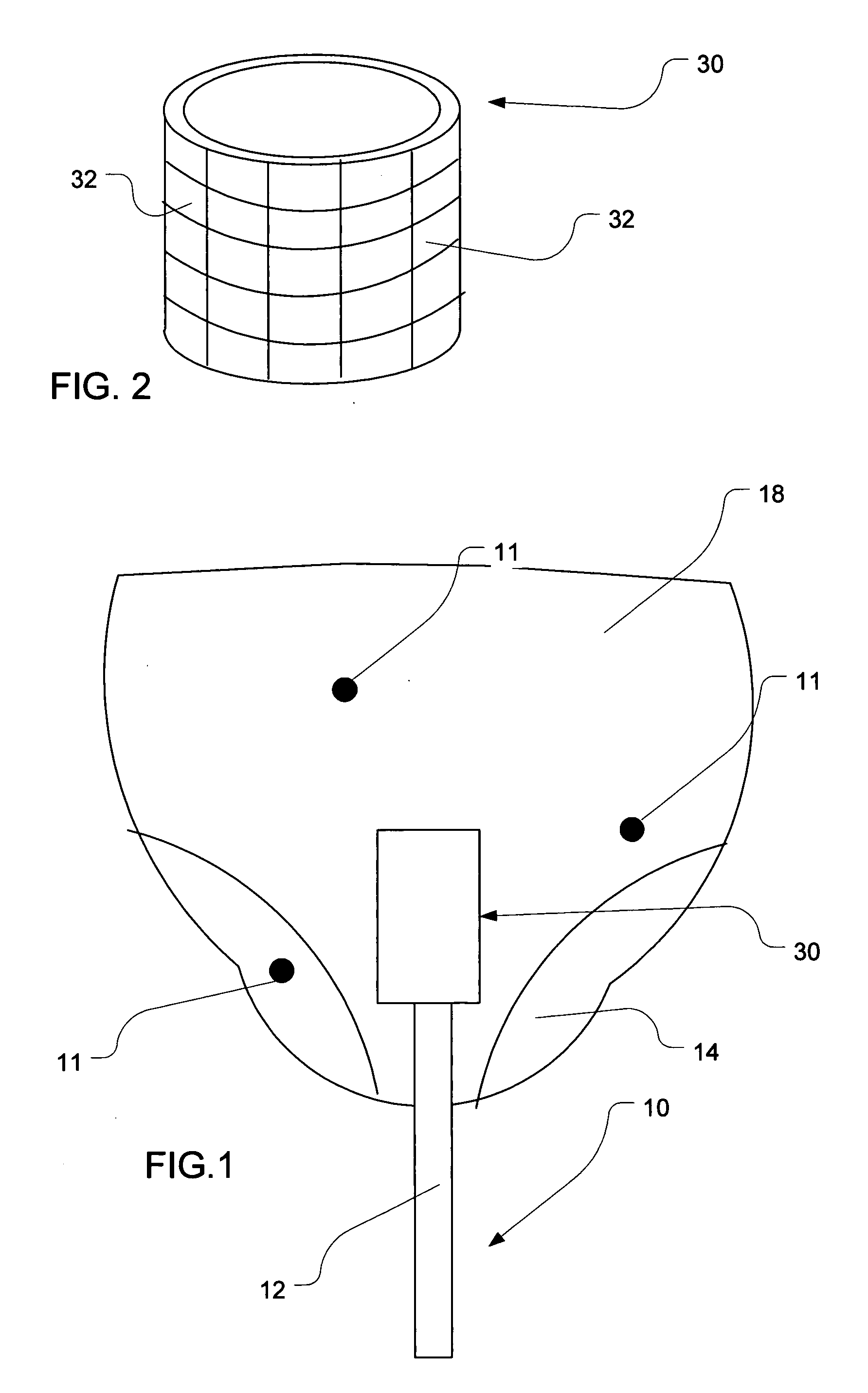
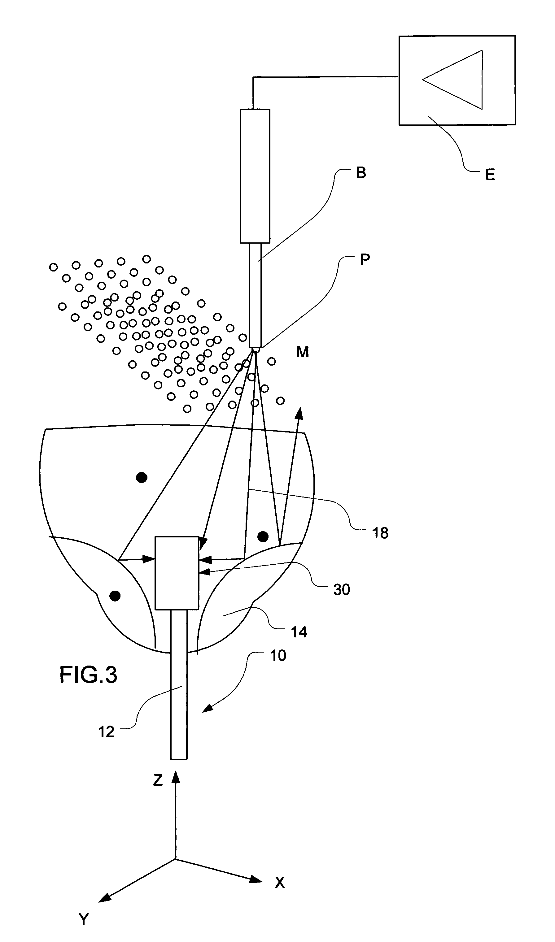
[0019] Turning now to the details of the drawings, FIG. 1 is a schematic representation of an embodiment of a probe in accordance with the present invention. A probe 10 includes a catheter 12 having a distal end bearing an outer, reflector balloon 14; an inner, structural balloon 18; and a transducer subassembly 30. U.S. Pat. No. 6,635,054 and International Publication WO 2004 / 073505, discussed above, disclose in more detail various probe structures of this type. Such disclosure is incorporated herein by reference.

[0020] Prior to use, the probe would be in a collapsed state, in which both balloons are collapsed about the transducer subassembly 30. Preferably, this probe is for use in cardiac ablation. Accordingly, it could be inserted over a guide wire, through a sheath which, in accordance with conventional practice, has previously been threaded through a patient's circulatory system and into the left atrium of the heart. However, there are other known techniques for positioning t...


PUM


Abstract

Ultrasound energy originating from an emitter at a number of predetermined positions is sensed by a plurality of duplex transducers in a predefined arrangement. Each transducer produces a sensor signal representing ultrasound energy sensed by it, and the sensor signals of each transducer are stored in association with the predetermined position producing the sensor signal. Thereafter, an ablation pattern corresponding to a group of the predetermined positions may be generated by actuating each transducer with a time-reversed version of the sensor signals stored in association with the group of positions. By placing the transducers in a predetermined spatial relationship to the heart, the ablation pattern may be formed on the ostium of a pulmonary artery. Preferably the predetermined positions correspond to a grid of dots that may be used to approximate virtually any shape.

Description

BACKGROUND OF THE INVENTION [0001] The present invention relates to a high intensity ultrasound ablation apparatus and probe, and a method utilizing the principle of time-reversed acoustics. Known for years, high intensity focused ultrasound (HIFU) recently became an effective and widespread medical therapy technique. An expected benefit of HIFU is the creation of a clinical effect in a desired, confined location within a body, without damage to intervening tissue. [0002] A broad and diverse range of HIFU therapies, from shock wave lithotripsy, ultrasound enhanced drug deliveries, immune response stimulation, to hemostasis, non-invasive surgery is now in use1. In HIFU therapy the acoustic field is focused to a target area. Absorption of high intensity ultrasound in a focal region causes a significant temperature rise, resulting in coagulative necrosis of the target tissue. The irreversible ablation within the focal zone is defined by ultrasound source geometry. 1 M. R. Bailey et al,...

Claims


Application Information

Patent Timeline
IPC IPC(8): A61H1/00
CPCA61B17/2202A61B2017/22027A61B17/2251A61B17/22029
Inventor SINELNIKOV, YEGORWARNKING, REINHARD
Owner KONINKLIJKE PHILIPS ELECTRONICS NV
Why Eureka
Try Eureka