Image pickup apparatus and control method therefor

Active Publication Date: 2021-08-24
CANON KK
View PDF36 Cites 3 Cited by
  • Summary
  • Abstract
  • Description
  • Claims
  • Application Information

AI Technical Summary

Benefits of technology

[0006]The present invention is made in view of the above-described inconvenience, and it is an object of the present invention to provide an image pickup apparatus that is able to acquire a video image of a user's preference without any user's particular operation.

Problems solved by technology

However, when a life log camera periodically and automatically shoots an image in a state where a user is wearing the life log camera, a video image that is not a user's preference may be acquired, and a video image of a moment that the user really wants may be not acquired.

Method used


Image

  • Image pickup apparatus and control method therefor
  • Image pickup apparatus and control method therefor
  • Image pickup apparatus and control method therefor

Examples


first embodiment

[0049]Configuration of Image Pickup Apparatus

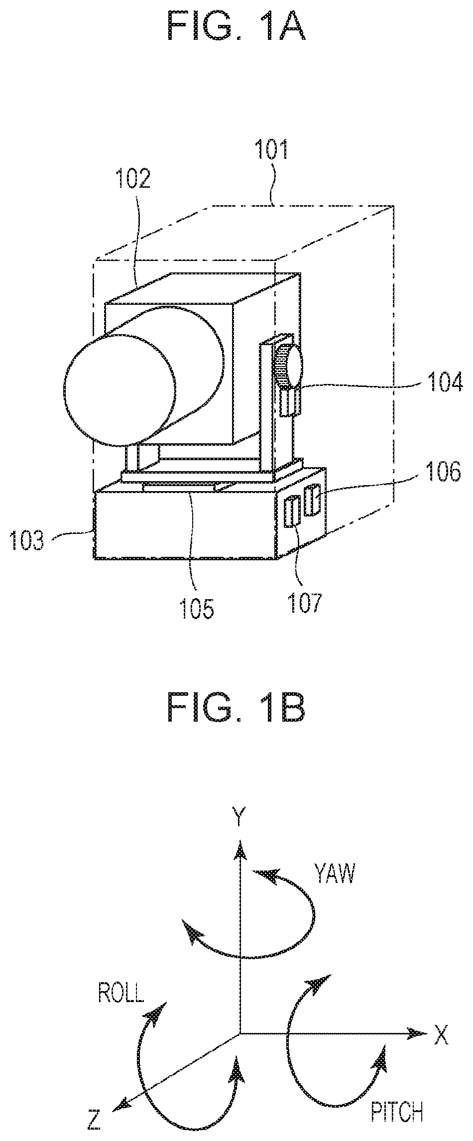
[0050]FIG. 1 is a diagram that schematically shows an image pickup apparatus of a first embodiment.

[0051]The image pickup apparatus 101 shown in FIG. 1A includes an operating member with which a power switch can be operated (hereinafter, referred to as power button; however, which may also be an operation, such as tapping, flicking, and swiping, on a touch panel), and other components. A lens barrel 102 that is a housing containing a shooting lens group and imaging element that capture an image is installed in the image pickup apparatus 101. The lens barrel 102 has a rotation mechanism that can drive and turn the lens barrel 102 with respect to a fixed part 103. A tilt unit 104 is a motor-driven mechanism that can turn the lens barrel 102 in a pitch direction shown in FIG. 1B. A pan unit 105 is a motor-driven mechanism that can turn the lens barrel 102 in a yaw direction. Thus, the lens barrel 102 is turnable around one or more axes. FIG....


PUM


Abstract

An image pickup apparatus is configured to change a shooting process based on data on a shot image. The image pickup apparatus is configured to, when the image pickup apparatus changes the shooting process, assign greater weights to the data on the shot image based on an instruction from a user than to the data on the shot image automatically processed.

Description

CROSS-REFERENCE TO RELATED APPLICATIONS[0001]This application is a Continuation of International Patent Application No. PCT / JP2018 / 034818, filed Sep. 20, 2018, which claims the benefit of Japanese Patent Application No. 2017-188938, filed Sep. 28, 2017, Japanese Patent Application No. 2017-254231, filed Dec. 28, 2017, and Japanese Patent Application No. 2018-053078, filed Mar. 20, 2018, all of which are hereby incorporated by reference herein in their entirety.TECHNICAL FIELD[0002]The present invention relates to an image pickup apparatus and a control method therefor.BACKGROUND ART[0003]In still image or video shooting with an image pickup apparatus, such as a camera, a user usually shoots an image by deciding a subject to be shot through a viewfinder, or the like, and adjusting the framing of the image to be shot through checking shooting conditions on his or her own. Such an image pickup apparatus has a function of detecting an error in user operation and informing the user of th...

Claims


Application Information

Patent Timeline
Patent Type & Authority Patents(United States)
IPC IPC(8): H04N5/232H04N5/225G03B17/02G03B15/00G03B17/56G03B5/00G03B7/091G03B17/00
CPCH04N5/232H04N5/2256G03B17/02G03B17/561G03B15/00G03B2205/0046H04N23/50H04N23/60H04N23/64H04N23/6812H04N23/687H04N23/695G03B5/00G03B7/091G03B17/56H04N23/51H04N23/55H04N23/54H04N23/58H04N23/61H04N23/62H04N23/80H04N23/667H04N23/69G03B17/00H04N23/56
Inventor WAKAMATSU, NOBUSHIGEOSAWA, SHINNOSUKEOGAWA, RYOTATSUIHIJI, YUKISHIMIZU, YUSUKE
Owner CANON KK
Why Eureka
Try Eureka