
System and Method of Image Improvement for Multiple Pulsed X-ray Source-in-Motion Tomosynthesis Apparatus Using Electrocardiogram Synchronization

Pending Publication Date: 2022-10-06
LIU JIANQIANG +3
View PDF0 Cites 0 Cited by
  • Summary
  • Abstract
  • Description
  • Claims
  • Application Information

AI Technical Summary

Benefits of technology

This patent describes a system and method for improving image acquisition in a tomosynthesis imaging apparatus. The system uses an electrocardiogram device to determine the cardiac cycle of a patient and use it to synchronize image acquisition. The system allows for faster image acquisition using multiple pulsed X-ray sources that can run at high speeds. The system also avoids the ECG peak pulse for better lung imaging under the influence of cardiac periodical motion. The multi-source tomosynthesis machine is already distributed to multiple X-ray sources that are spanned at a wide angle. The system can improve image quality and provide real-time and 4D imaging at multiple pulsed X-ray source-in-motion tomosynthesis imaging apparatus with low dose and high resolution. The system can also improve image quality for patients with low heart rates and can be used for cardiopulmonary tomosynthesis imaging.

Problems solved by technology

Therefore, when the object moves, if X-ray image exposures are underway, blurring images is inevitable.
However, conventional system haves only a single X-ray source at a cardiac rest with limited coverage and slow speed.
Further, there are maybe missing data at a specific angle if such single source system speeds up data acquisition and reconstructions may suffer from motion artifacts and / or limited view angle artifacts.

Method used


Image

  • System and Method of Image Improvement for Multiple Pulsed X-ray Source-in-Motion Tomosynthesis Apparatus Using Electrocardiogram Synchronization
  • System and Method of Image Improvement for Multiple Pulsed X-ray Source-in-Motion Tomosynthesis Apparatus Using Electrocardiogram Synchronization
  • System and Method of Image Improvement for Multiple Pulsed X-ray Source-in-Motion Tomosynthesis Apparatus Using Electrocardiogram Synchronization

Examples


Embodiment Construction

[0012]The present invention will be described in detail by example with reference to the attached drawings in the following paragraphs. Throughout this description, the preferred embodiment and examples shown should be considered exemplars rather than limitations on the present invention. As used herein, the “present invention” refers to any one of the embodiments of the invention described herein and any equivalents. Furthermore, reference to various feature(s) of the “present invention” throughout this document does not mean that all claimed embodiments or methods must include the referenced feature(s).

[0013]Thus, for example, it will be appreciated by those of ordinary skill in the art that the diagrams, schematics, illustrations, and such as represent conceptual views or processes illustrating systems and methods embodying this invention. The functions of the various elements shown in the figures may be provided through the use of dedicated hardware as well as hardware capable o...


PUM


Abstract

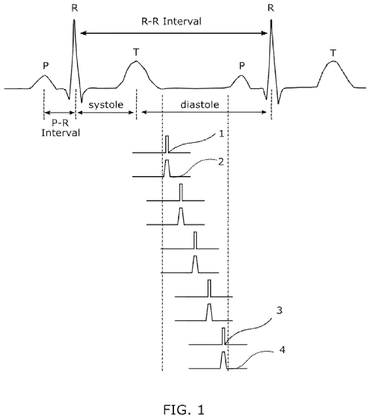
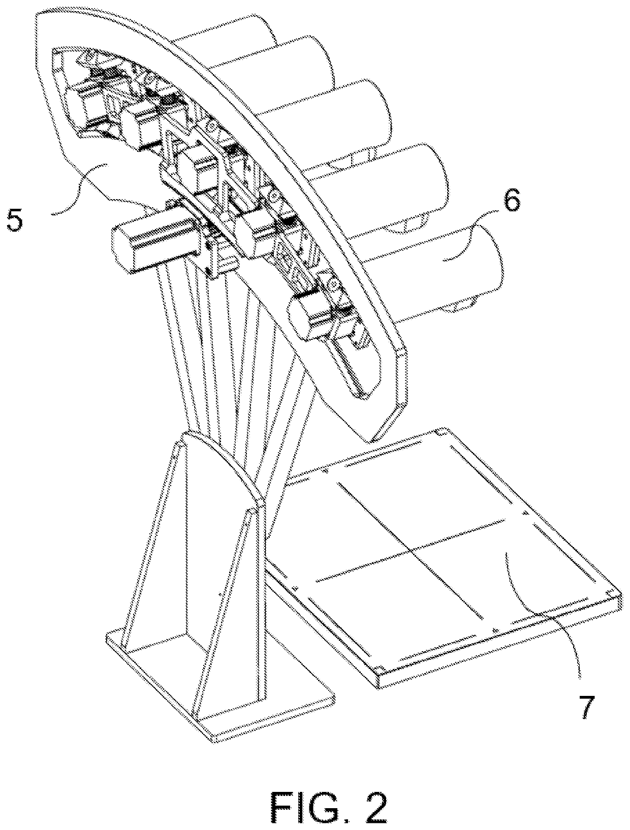
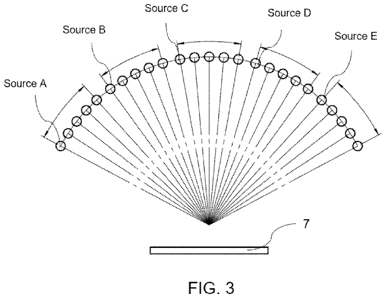
A system and method for improved image acquisition of multiple pulsed X-ray source-in-motion tomosynthesis imaging apparatus by generating the electrocardiogram (ECG) waveform data using an ECG device. Once a representative cardiac cycle is determined, system will acquire images only at rest period of heart beat. Real time ECG waveform is used as ECG synchronization for image improvement. The imaging apparatus avoids ECG peak pulse for better chest, lung and breast imaging under influence of cardiac periodical motion. As a result, smoother data acquisition, much higher data quality can be achieved. The multiple pulsed X-ray source-in-motion tomosynthesis machine is with distributed multiple X-ray sources that is spanned at wide scan angle. At rest period of one heartbeat, multiple X-ray exposures are acquired from X-ray sources at different angles. The machine itself has capability to acquire as many as 60 actual projection images within about two seconds.

Description

[0001]The present invention claims priority to Provisional Application Ser. Nos. 63 / 182,426 filed on Apr. 30, 2021; 63 / 226,508 filed Jul. 28, 2021; 63 / 170,288 filed Apr. 2, 2021, 63 / 175,952 filed Apr. 16, 2021, 63 / 194,071 filed May 27, 2021; 63 / 188,919 filed May 14, 2021; 63 / 225,194 filed Jul. 23, 2021; 63 / 209,498 filed Jun. 11, 2021; 63 / 214,913 filed Jun. 25, 2021; 63 / 220,924 filed Jul. 12, 2021; 63 / 222,847 filed Jul. 16, 2021; 63 / 224,521 filed Jul. 22, 2021; and U.S. application Ser. No. 17 / 149,133 filed Jan. 24, 2021, which in turn claims priority to Provisional Ser. 62 / 967,325 filed Jan. 29, 2020, the content of which is incorporated by reference.FIELD OF THE INVENTION[0002]The present invention relates to a system and method of multiple pulsed X-ray source in-motion tomosynthesis imaging apparatus for acquiring images of lung influenced by a periodically moving heart.BACKGROUND[0003]Digital tomosynthesis systems typically use an X-ray source mounted at one end of a rotatable ar...

Claims


Application Information

Patent Timeline
IPC IPC(8): A61B6/00A61B6/02G06T17/00
CPCA61B6/541A61B6/025A61B6/4007G06T17/00G06T2210/41G16H40/63G06V10/25G06V2201/03G06V10/12G06T11/005G06T2211/412G06T2211/436A61B6/5211A61B6/4283A61B6/4405A61B6/4482A61B6/542G01N23/044A61B6/032A61B6/06A61B6/4452A61B6/4476A61B6/467A61B6/56A61B6/583G01N23/083G01N23/18G01N2223/401G06T7/0012G06T11/006G06T2200/24G06T2207/10081G06T2207/20084G06T2207/30096A61B6/035A61B6/4014A61B6/4275A61B6/4441A61B6/482A61B6/0407A61B6/4208G06T7/11G16H10/60G16H30/20G16H50/20G06V2201/032G06V10/62G06T7/0016G06T2207/10076A61B6/08A61B6/4021A61B6/54G06T11/003G06T2207/20081G06T2207/30064G06T2207/30168A61B6/405A61B6/502
Inventor LIU, JIANQIANGMAOLINBAY, MANATKU, CHWEN-YUANYANG, LINBO
Owner LIU JIANQIANG
Learn More