Calibration of autonomous farming vehicle image acquisition system

Pending Publication Date: 2022-03-31
BLUE RIVER TECH
View PDF0 Cites 3 Cited by
  • Summary
  • Abstract
  • Description
  • Claims
  • Application Information

AI Technical Summary

Benefits of technology

[0005]A farming machine including an image acquisition system performs real-time calibration of the image acquisition system. The image acquisition system includes one or more cameras that captures images of a field as the farming machine travels through the field. Based on the captured images, a control system of the farming machine runs image segmentation or other detection methods to generate labelled images by identifying objects in the field and semantically labelling the identified objects and/or identifying pixel locations or boundary box corresponding to the identified objects. The objects may include static objects with known locations such as a building, lamppost, sign, or tree. The control system uses the labelled images in combination with motion data from an inertial measurement unit (IMU) and location data from a global positioning system (GPS) receiver to generate a three-dimensional (3D) model representative of the field (“represented 3D model”) in real time (for instance, using SLAM). Using the represented 3D model, the control system determines locations of one or more of the identified objects within the 3D model (“represented locations”). The control system compares the represented locations of the one or more identified objects to known reference locations of the one or more identified objects. A represented location and/or a reference location associate

Problems solved by technology

However, because farming machines are deployed in a variety of environments with different conditions, layouts, sizes, and because farming machines are used for different types of farming operations, it is difficult to implement a comprehe

Method used


Image

  • Calibration of autonomous farming vehicle image acquisition system
  • Calibration of autonomous farming vehicle image acquisition system
  • Calibration of autonomous farming vehicle image acquisition system

Examples


Embodiment Construction

I. Introduction

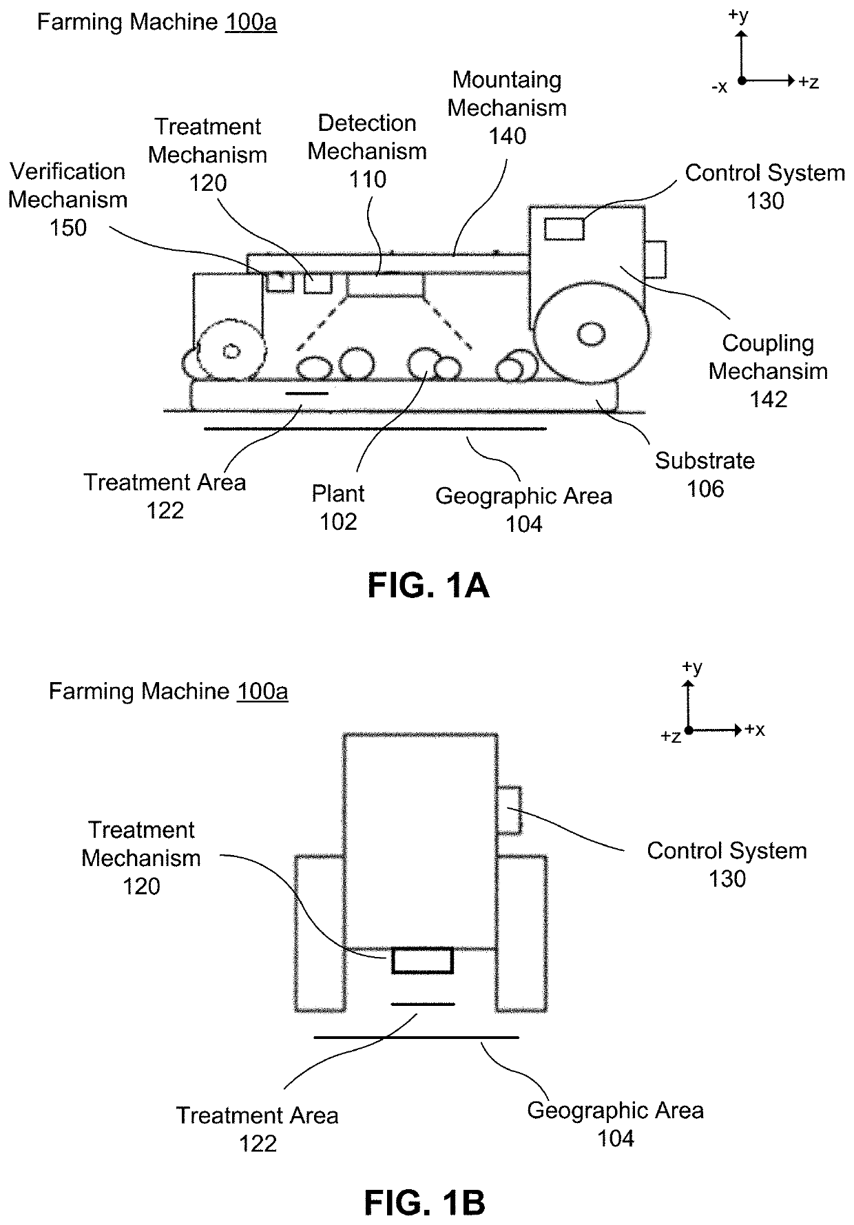
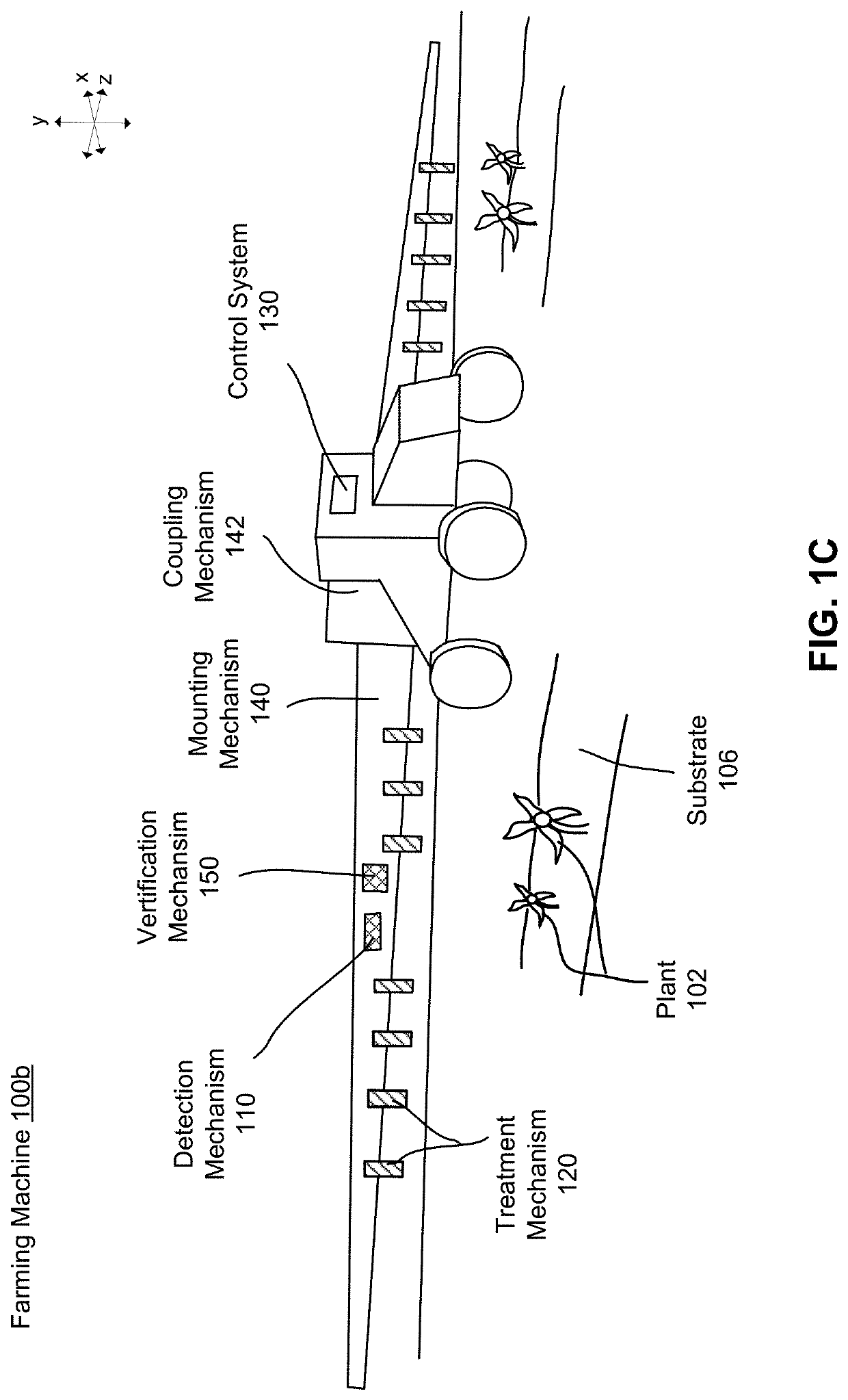
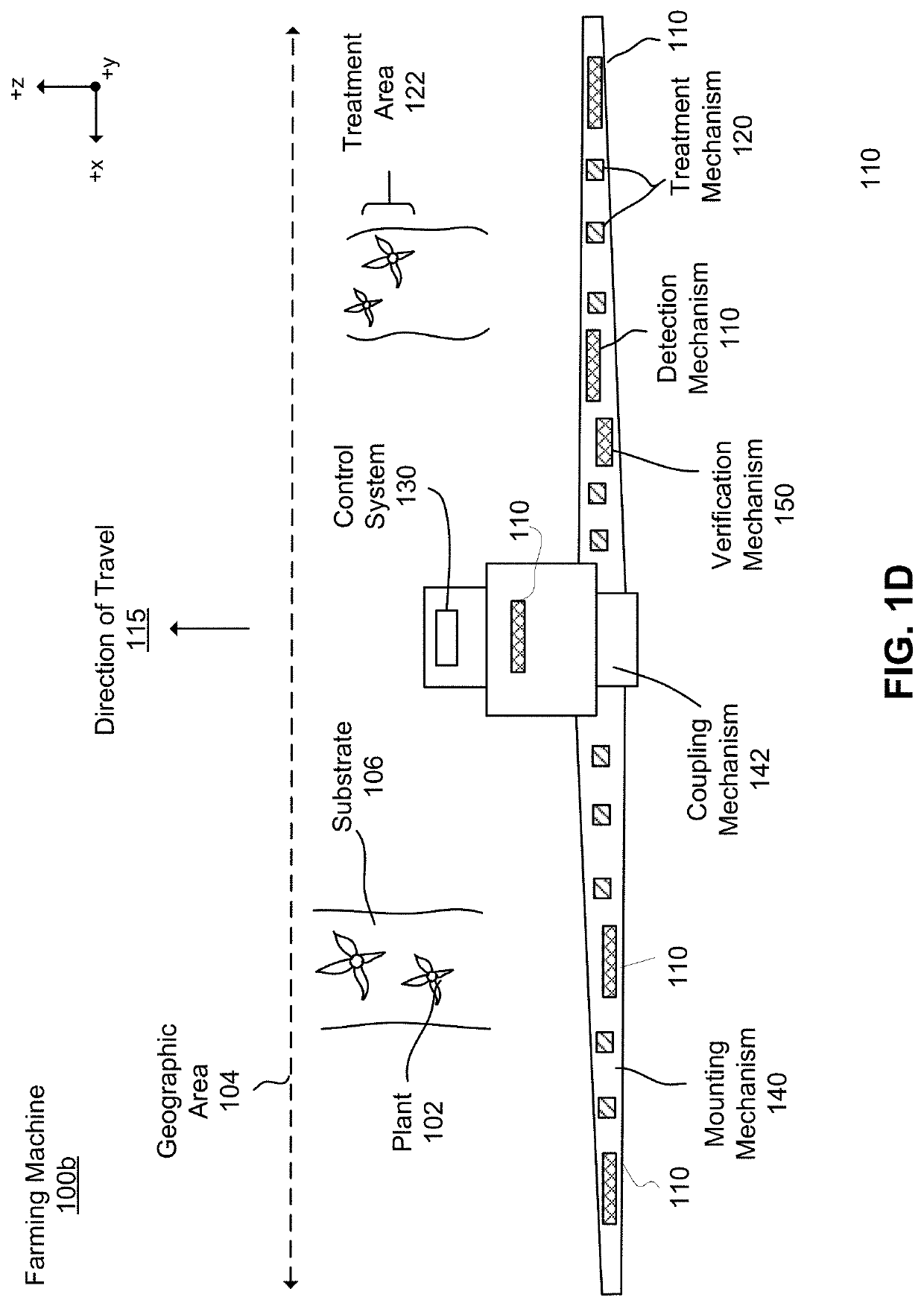
[0024]A farming machine includes an automated or semi-automated system for performing farming operations. A farming operation performed by the farming machine may be identifying and treating plants in a field. The farming machine employs an image acquisition system to detect plants for treatment as the farming machine travels through the field. The image acquisition system includes a plurality of image sensors (e.g., cameras) physically coupled to the farming machine to capture images of one or more plants. A control system identifies plants in the images and actuates treatment mechanisms coupled to the farming machine to treat the identified plants based on the images. As such, the farming machine is configured to target and treat plants individually, thus reducing waste and preventing unwanted plant growth resulting from treatments that are applied liberally across a field. Another farming operation performed by the farming machine may be tilling the field in prepar...


PUM


Abstract

A system and a method are disclosed for calibrating an image acquisition system of a farming machine. The farming machine captures images of objects in an environment as the farming machine moves through an environment. Based on the captured images, a represented three-dimensional (3D) model of the environment representing the objects in a three-dimensional space is generated. From the represented 3D model, a represented location of an object (e.g., building, lamppost, tree) is determined. The represented location of the object is compared to a reference location of the object and the comparison is used to calibrate the image acquisition system by modifying positions, orientations, or optical settings of one or more cameras in the image acquisition system.

Description

CROSS REFERENCE TO RELATED APPLICATIONS[0001]This application claims the benefit of U.S. Provisional Application No. 63 / 084,751 filed Sep. 29, 2020, which is incorporated in its entirety herein by this reference.BACKGROUNDField of Disclosure[0002]This disclosure generally relates to farming technology, in particular to calibrating an image acquisition system of a farming machine.Description of the Related Art[0003]Conventional farming machines for performing farming operations such as plowing, tilling, planting, and treating plants may be equipped with sensors to gather data about conditions of its environment. Using the data, the farming machines autonomously or semi-autonomously determines instructions for traversing through the field while performing the farming operations. In particular, the sensors of the farming machines may include an image acquisition system that includes one or more cameras used to capture images of the environment, and the farming machines may use visual i...

Claims


Application Information

Patent Timeline
IPC IPC(8): G06T7/80G06T7/70G06T7/579G06T17/05G05D1/02
CPCG06T7/80G06T7/70G05D2201/0201G06T17/05G05D1/0246G06T7/579G06T7/74G06T2207/30204G06V20/56G06V20/647G06V20/58
Inventor NIDAY, TYLER CALVINOEZDEMIR, UGUR
Owner BLUE RIVER TECH
Why Eureka
Try Eureka