Ultrasound diagnosis system including a motor driving multiplane ultrasound probe and image data acquiring method

a multi-plane ultrasound and ultrasound probe technology, applied in the field of ultrasound diagnosis system including ultrasound probe, can solve the problems of deteriorating image data quality, difficult to insert the head portion into the esophagus of a patient without causing the patient to experience pain, etc., and achieve the effect of preventing the acquisition of image data

Inactive Publication Date: 2011-12-13
TOSHIBA MEDICAL SYST CORP
View PDF18 Cites 0 Cited by
  • Summary
  • Abstract
  • Description
  • Claims
  • Application Information

AI Technical Summary

Benefits of technology

[0014]To solve the above-mentioned conventional problems and defects, the present invention provides a new ultrasound diagnosis system including a reverse rotation motor driving multi-plane ultrasound probe and a scanning method. The ultrasound diagnosis system including a motor drive multi-plane type ultrasound probe consistent with the present invention can automatically rotate the transducers in a first direction to acquire image data in a prescribed target angle and the transducers are automatically rotated in a reverse direction at a high speed so as to acquire image data secretive to the image data acquired at the target angle by rotating the transducers in the first direction. The scanning method consistent with the present invention can automatically place successive scanning planes over a target angle in a designated rotation direction. When the motor driven transducers reach a target angle in a first direction for acquiring image data, the transducers are automatically reversed to operate in a second direction by reserving the transducers at a high speed with ceasing acquisition of image data. After completing the reversion, the transducers are again rotated in the first direction to acquire image data at successive rotation angles.
[0015]According to an ultrasound diagnosis system including a motor driving multi-plane type ultrasound probe for use with the present invention, because the transducers are automatically rotated in a reverse direction at a higher speed when a rotated angle of the transducers exceeds a target angle, a user or operator can freely place the scanning planes not withstanding a limited angle range of rotation. Thus, it becomes possible to set a scanning plane in a short time. Further, according to the present invention, it become possible to make a tip portion of a motor driving multi-plane type ultrasound probe in a small size by coupling to the ultrasound diagnosis system through a flexible probe cable in order to control the scanning planes of the transducers. Consequently, it can reduce pain to a patient. An ultrasound probe consistent with the present invention can set a target rotation range of a plurality of transducers from an angle of zero degrees to an angle over 180 degrees. This can restrict frequent occurrences of reversing operations to as few as possible. This is beneficial to reduce displayed image due to frequent freezes of displayed images as a result of frequent reverse operations. Further, according to the present invention, it can reduce the load to a rotation drive mechanism for the transducers.

Problems solved by technology

The successive rotation type probe has various problems and defects.
Consequently, it becomes difficult to insert the head portion into an esophagus of a patient without causing the patient to experience pain.
Further, the slipping noises generated from the slip ring cause deteriorations in the quality of the generated image data to occur.
These operations are complicated and burdensome for an operator.
Thus, it takes a lot of time for setting the transducers in a desired angle position.
Since it largely reduces efficiencies of observations through ultrasound images, the conventional reverse rotation type motor driving multi-plane ultrasound probe also has serious problems.

Method used


Image

  • Ultrasound diagnosis system including a motor driving multiplane ultrasound probe and image data acquiring method
  • Ultrasound diagnosis system including a motor driving multiplane ultrasound probe and image data acquiring method
  • Ultrasound diagnosis system including a motor driving multiplane ultrasound probe and image data acquiring method

Examples


Embodiment Construction

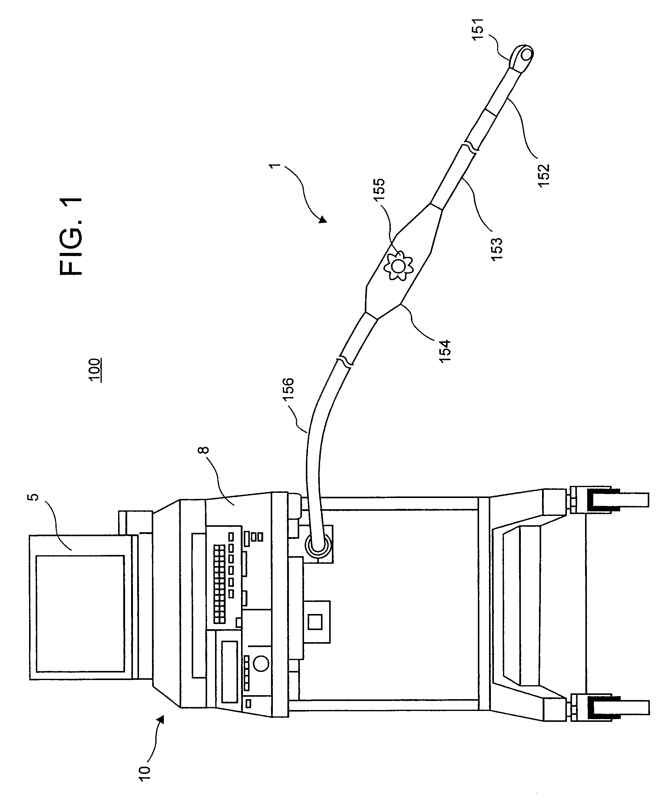
[0045]As shown in FIG. 1, an ultrasound diagnosis system 100 consistent with the present invention is comprised of a diagnosis main body 10 and a motor drive multi-plane ultrasound probe 1 coupled to the diagnosis main body 10 in order to transmit and receive ultrasound to and from a diagnosis object portion of a patient. The motor drive multi-plane ultrasound probe 1 is electrically connected to the main body 10 through a tip portion 151 for insertion into a patient body, for example an esophagus of the patient, an angle portion 152, a flexible trans-guiding portion 153 and a knob handling portion 154 that is connected to the trans-guiding portion 153. The tip portion 151 and the angle portion 152 are inserted into a target position in a patient's body through the trans-guiding portion 153.

[0046]As shown in FIG. 3, the tip portion 151 of the ultrasound probe 1 includes a head portion 11 and a rotation drive mechanism 12. As shown in FIG. 4, the head portion 11 provides a plurality ...


PUM


Abstract

An ultrasound diagnosis system including a motor driving multi-plane ultrasound probe for acquiring image data at a voluntary scanning plane in a body of a patient is provided. The data acquisition is performed by driving rotation of a plurality of transducers arranged in a head portion of the probe toward a target angle of a prescribed rotation range by driving an arranged surface of the plurality transducers so as to make a plurality of scanning planes toward a first direction in a normal mode. The driving direction of the head portion is automatically reversed by 180 degrees to a second direction opposite to the first direction at a high speed in a reverse mode when the rotation angle of the head portion arrives at the target angle. The reversed head portion can continue to acquire image data at the same scanning planes to the previous scanning planes of the rotation drive to the first direction.

Description

CROSS-REFERENCE TO RELATED APPLICATIONS[0001]This application claims priority to, and the benefit of, Japanese Patent Application No. 2007-99245, filed on Apr. 5, 2007, the contents of which are expressly incorporated herein by reference, in their entirety.BACKGROUND OF THE INVENTION[0002]A. Field of the Invention[0003]The present invention relates to an ultrasound diagnosis system including an ultrasound probe, and more particularly, to an ultrasound diagnosis system including a motor driving multi-plane type ultrasound probe that can acquire image data at a plurality of scanning planes, by rotating an arranged surface of ultrasound transducers in a head portion of the probe across a prescribed range of angles.[0004]B. Background of the Invention[0005]An ultrasound diagnosis system transmits ultrasound from ultrasound transducers (hereinafter: “transducers) installed in a head portion of the ultrasound probe to an object, such as a patient. The transducers receive ultrasounds refle...

Claims


Application Information

Patent Timeline
Patent Type & Authority Patents(United States)
IPC IPC(8): A61B8/00A61B8/14
CPCA61B8/08A61B8/12A61B8/4461
Inventor SHIKATA, HIROYUKIKOSAKU, HIDEKITAKEUCHI, TAKASHI
Owner TOSHIBA MEDICAL SYST CORP
Why Eureka
Try Eureka